Gas well automatic water draining plunger

An automatic drainage and plunger technology, applied in machine/engine, wellbore/well components, liquid fuel engine, etc., can solve problems such as process failure, increase workover operations, reduce plunger life, etc., to avoid excessive liquid leakage , The effect of improving the success rate of drainage and reducing management costs

Active Publication Date: 2017-03-22
CHINA PETROLEUM & CHEM CORP +1
View PDF11 Cites 21 Cited by
  • Summary
  • Abstract
  • Description
  • Claims
  • Application Information

AI Technical Summary

Problems solved by technology

[0005] However, too low or too high operation frequency of the plunger is not conducive to drainage and gas recovery. The reason is that when the drainage frequency is too low, the liquid will form accumulation, which will cause excessive liquid load on the upper part of the plunger, and the plunger may not reach the wellhead , resulting in process failure, and increased workover operations; and when the drainage frequency is too high, the bottom of the well is not fully formed liquid accumulation, and the bottom hole pressure recovery time is short, the plunger rises slowly, the residence time is long, and the liquid leakage is serious, reducing the At the same time, the no-load operation of the plunger will aggravate the wear of the plunger and reduce the life of the plunger. Therefore, blindly pursuing a higher falling speed and operating frequency cannot achieve the best gas well drainage effect.
It can be seen that the technical problem commonly faced by the existing drainage plunger is: how to realize the intellectualization of drainage and obtain the best drainage frequency

Method used


Image

  • Gas well automatic water draining plunger
  • Gas well automatic water draining plunger
  • Gas well automatic water draining plunger

Examples


Embodiment Construction

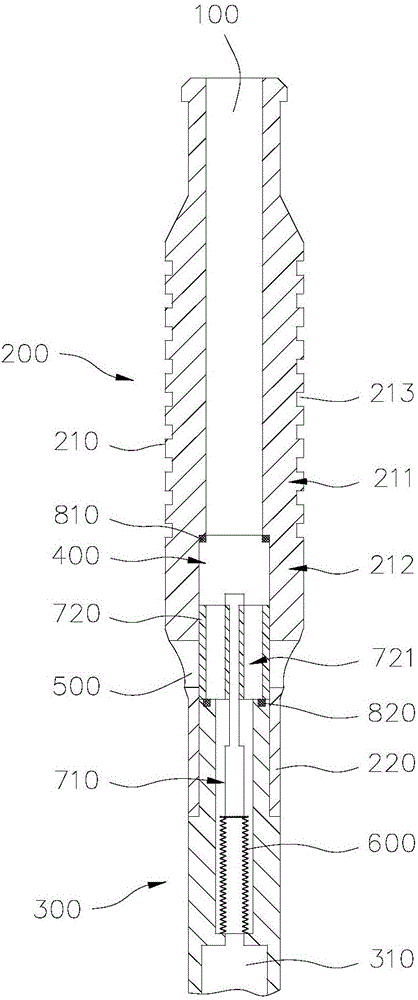
[0036] Such as figure 1 and Figure 5 As shown, the gas well automatic drainage plunger of the present invention includes a plunger cylinder body provided with a through hole 100 in the axial direction. The control mechanism of the plunger cylinder at least includes a first cylinder unit 210 and a second cylinder unit 220 with outer diameters from large to small, and the first cylinder unit 210 and the second cylinder unit 220 are provided with a limit The position groove 400, the second cylinder unit 220 is provided with a bypass channel 500 that can communicate with the through hole 100 along the radial direction of the limit groove 400, and the control mechanism is provided with the upper chamber and the lower chamber. The pressure difference between the chambers is transformed into an elastic sensitive element 600 for axial displacement, and the elastic sensitive element 600 is connected to and can slide reciprocally along the limit groove 400 under the action of the elas...


PUM


Abstract

The invention relates to a gas well automatic water draining plunger. The gas well automatic water draining plunger comprises a plunger barrel with a through hole formed in the axial direction. The plunger barrel is internally provided with a control mechanism partitioning the through hole into an upper cavity and a lower cavity. The plunger barrel at least comprises a first barrel unit and a second barrel unit, and the outer diameter of the first barrel unit is greater than that of the second barrel unit. The first barrel unit and the second barrel unit are internally provided with limiting grooves. The second barrel unit is provided with a bypass channel which can communicate with the through hole in the radial direction of the limiting groove. The control mechanism is provided with an elastic sensitive element capable of converting differential pressure between the upper cavity and the lower cavity into axial displacement, and an actuating element which is connected with the elastic sensitive element and is capable of sliding back and forth along the limiting groove under the action of the elastic sensitive element so as to open / close the bypass channel. The plunger can control the bypass channel to open / close through the elastic sensitive element according to changes of the well bottom dropsy degree while achieving non-shut-in continuous production, automatic liquid draining is achieved, and the liquid draining frequency is controlled to be the optimal level.

Description

technical field [0001] The invention relates to the field of oil and gas exploitation, in particular to a gas well automatic drainage plunger. Background technique [0002] During the production of natural gas wells, a certain amount of condensate water or formation water is usually produced. When the gas production rate decreases below the critical gas volume carrying liquid, the gas flow velocity is not enough to bring the water out of the wellbore. At this time, the bottom hole will occur. Fluid accumulation causes rapid production reduction or even shutdown of gas wells. Therefore, how to effectively remove the bottom-hole accumulation has become the key to the stable production of gas wells in the middle and late stages. [0003] The plunger drainage gas recovery process is a drainage process that uses the mechanical interface of the plunger to separate the gas from the lifted liquid, reduce gas channeling and liquid fallback, and periodically lift liquid in the tubing...

Claims


Application Information

Patent Timeline
Patent Type & Authority Applications(China)
IPC IPC(8): E21B43/12E21B43/00F04B53/14
CPCE21B43/00E21B43/121F04B53/14
Inventor 刘通王世泽陈海龙张国东赵哲军姚麟昱倪杰许剑
Owner CHINA PETROLEUM & CHEM CORP
Why Eureka
Try Eureka