Underground stabilized pressure gas storage device with built-in water storage container

A water storage container and gas storage device technology, applied in the geometry/arrangement/dimension of container structure, adjustable capacity gas storage tank, gas/liquid distribution and storage, etc., can solve the problem that the soluble salt layer wall does not allow long-term Water contact and other problems, to achieve the effect of being conducive to stable operation, avoiding repeated fluctuations, and saving construction costs

Active Publication Date: 2018-12-28
NORTH CHINA ELECTRIC POWER UNIV (BAODING)
View PDF5 Cites 0 Cited by
  • Summary
  • Abstract
  • Description
  • Claims
  • Application Information

AI Technical Summary

Problems solved by technology

Add water in the gas storage device, control and adjust the inflow and outflow of liquid to stabilize the pressure of the gas storage container, but the soluble salt layer wall does not allow long-term contact with water, so how to avoid the salt cavern gas storage device in the prior art Inner wall contact with water has become a technical problem to be solved urgently in this technical field

Method used


Image

  • Underground stabilized pressure gas storage device with built-in water storage container
  • Underground stabilized pressure gas storage device with built-in water storage container
  • Underground stabilized pressure gas storage device with built-in water storage container

Examples


Embodiment Construction

[0023] In order to make the purpose, technical solutions and advantages of the present invention more clear, the following will be combined with the appendix in the embodiment of the present invention. Figure 1-3 , The technical solution in the embodiment of the present invention will be described in more detail.

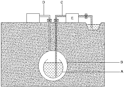
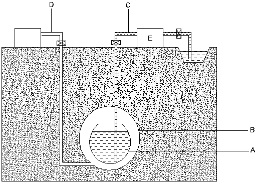
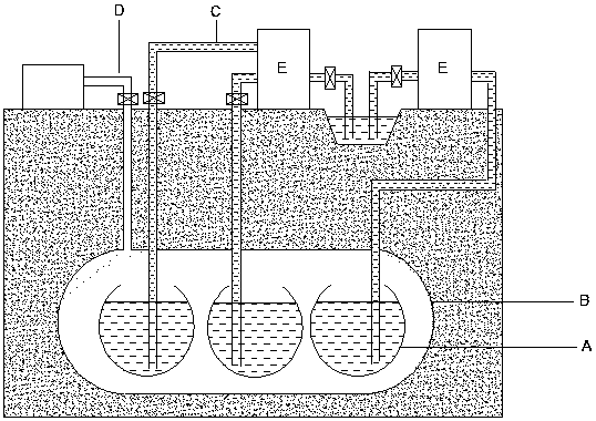
[0024] figure 1 It is a schematic structural diagram of an underground stabilized gas storage device with a built-in water storage container of the present invention. The water storage container A is placed inside the underground gas storage container B through a certain supporting structure, the lower part is closed, and the upper part communicates with the gas storage container B. One end of the liquid pipe C passes through the wall of the gas storage container B and is connected to the bottom of the water storage container A, and the other end Connect to one end of the liquid driving device E, the other end of the liquid driving device E is connected to the externa...


PUM


Abstract

The invention belongs to the field of underground gas storage, and discloses an underground pressure-stabilized gas storage device with a built-in water storage container, and a pressure stabilization control technology thereof. The water storage container is located inside the underground gas storage container. The lower portion of the water storage container is closed, and the upper portion of the water storage container communicates with a gas storage container. One end of a liquid pipeline penetrates through the wall of the gas storage container to be connected to the bottom of the water storage container, and the other end of the liquid pipeline is connected to one end of a liquid drive device; and the other end of the liquid drive device is connected with an outer water storage device. One end of a gas pipeline is connected with the gas storage container, and the other end of the gas pipeline is connected with an outer pneumatic device; and the outer pneumatic device injects compressed air into the gas storage container or guides the compressed air out of the gas storage container. The pressure stabilization control scheme has the following two control targets of (1) the pressure intensity of gas in the gas storage container, and (2) the difference of the pressure intensity of liquid at the two ends of the liquid drive device. The water storage container is arranged in the underground gas storage device, direct contact between water and the inner wall of the gas storage container is avoided, and an implement mode is provided for soluble salt cavern gas storage and gas storage adopting a metal container which is prone to corrosion of water; and meanwhile, the pressure stabilization control scheme is adopted for facilitating safe and stable operation of the gas storage device.

Description

Technical field [0001] The invention relates to the field of underground gas storage, in particular to an underground pressure-stabilizing gas storage device with a built-in water storage container and its pressure-stabilizing control technology. Background technique [0002] The energy storage system is an important link in maintaining the stability of the power grid and ensuring the reliability of power supply, and provides an effective way to solve the large-scale grid integration of renewable energy. Compressed air energy storage technology is an important way to effectively solve large-scale energy storage problems due to its advantages such as small geographical conditions, large capacity, long working hours, good economic performance, and multiple charge and discharge cycles. [0003] Compressed air energy storage system is a hot spot in the research and development of large-scale electric energy storage technology, and the gas storage device is one of its important componen...

Claims


Application Information

Patent Timeline
Patent Type & Authority Patents(China)
IPC IPC(8): F17B1/12F17B1/14F17B1/16
CPCF17B1/12F17B1/14F17B1/16F17C2201/0128
Inventor 姜彤全璐瑶张璐路
Owner NORTH CHINA ELECTRIC POWER UNIV (BAODING)
Why Eureka
Try Eureka