
Mass and flow measuring method and device of refrigerant in refrigerating system and measuring instrument

A refrigeration system and mass flow technology, applied in the direction of refrigeration and liquefaction, refrigerators, refrigeration components, etc., can solve the problems of on-site measurement of unsuitable units, destruction of refrigeration system units, damage to refrigeration system units, etc.

Inactive Publication Date: 2017-03-22
TSINGHUA UNIV
View PDF3 Cites 50 Cited by
  • Summary
  • Abstract
  • Description
  • Claims
  • Application Information

AI Technical Summary

Problems solved by technology

Refrigerant mass flow rate is an important parameter to judge whether the refrigeration system is running normally. Currently, the measurement method of refrigerant mass flow rate is obtained by Coriolis mass flow meter, but this method is not suitable for on-site measurement of unit performance. The main reason is that the Coriolis mass flowmeter needs to be welded on the liquid phase pipe at the outlet of the condenser, which will cause damage to the running refrigeration system unit, and the user acceptance is poor
[0004] Therefore, how to overcome the defect that the refrigerant mass flow measurement method in the prior art will destroy the refrigeration system unit has become a technical problem to be solved urgently

Method used


Image

  • Mass and flow measuring method and device of refrigerant in refrigerating system and measuring instrument
  • Mass and flow measuring method and device of refrigerant in refrigerating system and measuring instrument
  • Mass and flow measuring method and device of refrigerant in refrigerating system and measuring instrument

Examples


Embodiment 1

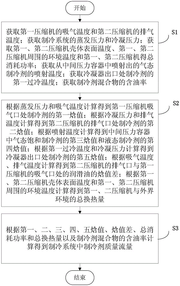
[0055] This embodiment provides a method for measuring the mass flow rate of refrigerant in a refrigeration system. The refrigeration system includes an evaporator, a first compressor, a second compressor, a condenser, and an intermediate pressure vessel (here the intermediate pressure vessel may be a flasher) , can also be an intercooler) and a throttle valve, the outlet of the evaporator is connected to the inlet of the first compressor, the outlet of the first compressor is connected to the inlet of the second compressor, and the outlet of the second compressor is connected to the inlet of the condenser ,Such as figure 1 As shown, the method is as follows:

[0056] S1: Obtain the suction temperature of the first compressor and the discharge temperature of the second compressor; obtain the evaporation pressure and condensation pressure of the refrigeration system; obtain the shell surface temperature of the first and second compressors, the first and second compression The ...

Embodiment 2

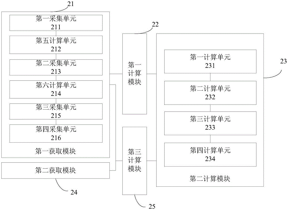
[0076] This embodiment provides a measurement device for refrigerant mass flow in a refrigeration system. The refrigeration system includes: an evaporator, a first compressor, a second compressor, a condenser, and an intermediate pressure vessel (the intermediate pressure vessel may be a flash The outlet of the evaporator is connected to the inlet of the first compressor, the outlet of the first compressor is connected to the inlet of the second compressor, and the outlet of the second compressor is connected to the inlet of the condenser entrance, such as figure 2 As shown, the device includes:

[0077] The first obtaining module 21 is used to obtain the suction temperature of the first compressor and the discharge temperature of the second compressor; obtain the evaporation pressure and the condensation pressure of the refrigeration system; obtain the first and second compressor casing surface temperatures, The ambient temperature around the first and second compressors an...

Embodiment 3

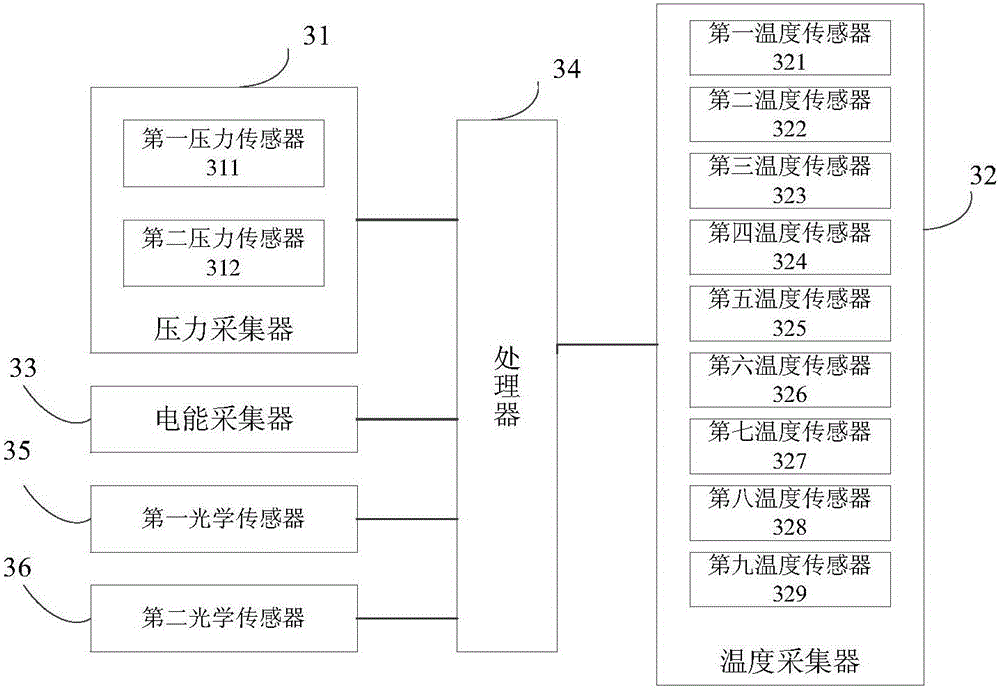
[0093] This embodiment provides a measuring instrument for refrigerant mass flow in a refrigeration system, such as image 3As shown, the device includes: a processor 34 and a pressure collector 31 connected to the processor 34, a temperature collector 32 and an electric energy collector 33. In practical applications, by combining the pressure collector 31, the temperature collector 32 and the electric energy collector Devices 33 are respectively deployed in the refrigeration system to collect the operating parameters of the refrigeration system in real time, such as Figure 4 As shown, the refrigeration system may include: an evaporator 41, a first compressor 421, a second compressor 422, a condenser 43, a flasher 44 (that is, the flasher 44 here is an intermediate pressure vessel) and a throttle valve 45, the outlet of the evaporator 41 is connected to the inlet of the first compressor 421, the outlet of the first compressor 421 is connected to the inlet of the second compre...


PUM


Abstract

The invention provides a mass and flow measuring method and a device of a refrigerant in a refrigerating system and a measuring instrument. The method comprises the steps of: obtaining an intake temperature of a first compressor, an exhaust temperature of a second compressor, an evaporation pressure, a condensation pressure, shell surface temperatures of the first and second compressors, a surrounding environment temperature, a total consumption power, a spraying temperature, a first supercooling temperature, a second supercooling temperature and an oil content of a refrigerant mixture; calculating corresponding first, second, third, fourth and fifth enthalpy values, enthalpy value differences and total heat exchange quantities of the first and second compressors with external environment according to the obtained data; and calculating the mass and the flow of the refrigerant in the refrigerating system according to the first, second, third, fourth and fifth enthalpy values, the enthalpy value differences, the total consumption power, the total heat exchange quantities and the oil content of the refrigerant mixture. The method realizes non-invasion and high-precision measurement of the mass and the flow of the refrigerant in the refrigerating system, prevents adverse effect on the refrigerating system in the measuring process, and improves the user experience.

Description

technical field [0001] The invention relates to the field of refrigeration system analysis, in particular to a method, device and measuring instrument for measuring refrigerant mass flow in a refrigeration system. Background technique [0002] The refrigeration system is a machine that transfers the heat of a cooled object with a lower temperature to the ambient medium to obtain cold energy. The working medium that participates in the thermodynamic process change (energy conversion and heat transfer) in the refrigeration system is called refrigerant. Refrigeration systems generally consist of compressors, condensers, evaporators, and throttle valves, and some refrigeration systems also include intermediate pressure vessels (such as flashers or intercoolers). With the development of human society, in many occasions, the compressor needs to work under the condition of a large compression ratio, and the traditional single-stage compression technology will cause the exhaust temp...

Claims


Application Information

Patent Timeline
IPC IPC(8): F25B1/10F25B49/02
CPCF25B1/10F25B49/02F25B2313/031F25B2500/19F25B2700/1931F25B2700/1933F25B2700/21151F25B2700/21152F25B2700/2117F25B2700/21163
Inventor 石文星王宝龙黄文宇张国辉李先庭丁连锐
Owner TSINGHUA UNIV
Learn More