Eureka AIR delivers breakthrough ideas for toughest innovation challenges, trusted by R&D personnel around the world.

Method for setting calibration block for phased-array ultrasonic testing of bimetal composite material

A composite material and phased array technology, which is applied in the direction of material analysis, measurement device, and material analysis using sonic/ultrasonic/infrasonic waves to ensure welding quality, improve reliability and on-site inspection efficiency.

Active Publication Date: 2017-03-22
CHINA NAT OFFSHORE OIL CORP +1
View PDF8 Cites 9 Cited by
  • Summary
  • Abstract
  • Description
  • Claims
  • Application Information

AI Technical Summary

Problems solved by technology

[0004] The main purpose of the present invention is to overcome the above-mentioned shortcomings existing in the prior art, and to provide a method for setting up the calibration test block of the bimetallic composite material phased array probe, which can not only effectively meet the requirements for the bimetallic composite material submarine pipeline. The detection requirements solve the problem that the calibrated phased array system detects different types of defects in each position; moreover, it also improves the reliability of the entire phased array system and the efficiency of on-site inspection, ensuring the welding quality

Method used


Image

  • Method for setting calibration block for phased-array ultrasonic testing of bimetal composite material
  • Method for setting calibration block for phased-array ultrasonic testing of bimetal composite material
  • Method for setting calibration block for phased-array ultrasonic testing of bimetal composite material

Examples


Embodiment Construction

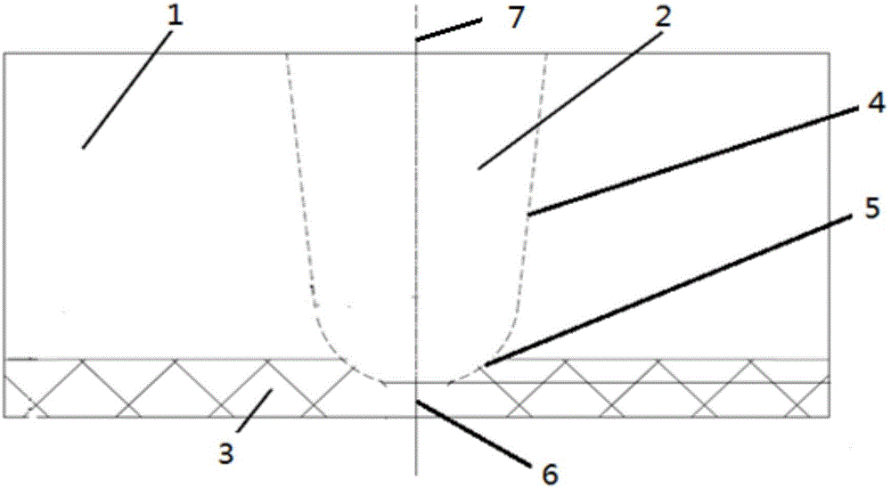
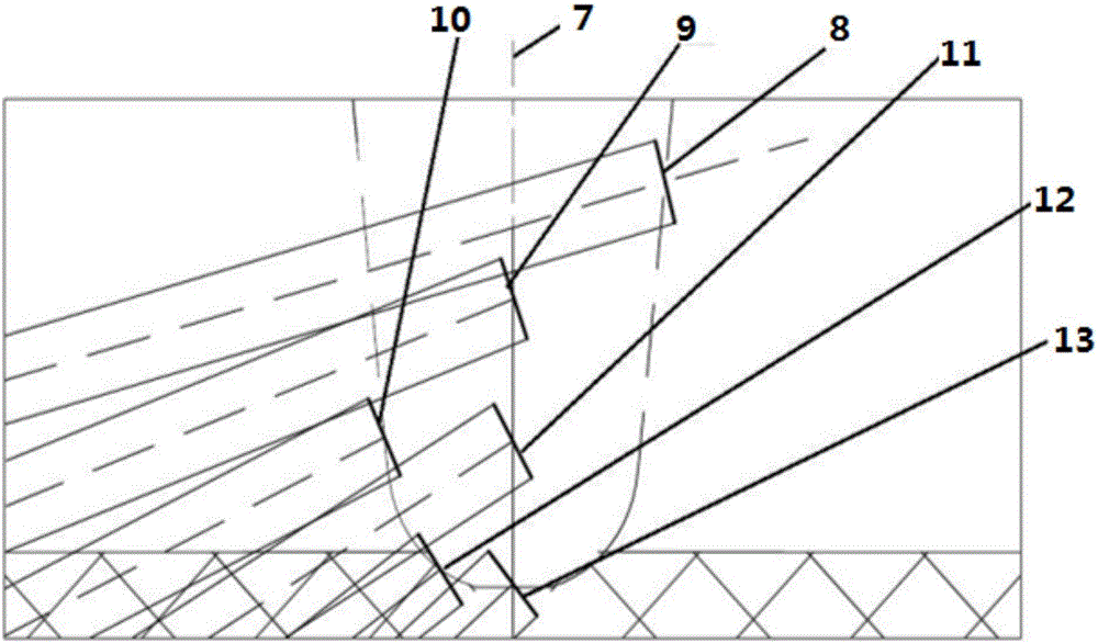
[0032] Such as figure 1 — Image 6 As shown, in this embodiment: the size of the pipeline is 10”x18.9mm, the groove form 4 in the filling area is a J-shaped groove, the base material 1 is made of carbon steel, the anti-corrosion layer 3 at the root is stainless steel with a thickness of 3mm, and the weld filling area 2 is made of nickel base.

[0033] The present invention adopts following specific steps:

[0034] Step 1: Partition the test block according to the groove form 4 of the filling area approved by the welding process, and the height of each partition is 2.5mm, and the root is an independent partition;

[0035] Step 2: According to the combined performance of the phased array probe (AUT) used, set test reflectors at different positions on the groove surface of the filling area, place the probe on the opposite side of the reflector, and select a longitudinal wave test. Move the probe to measure the signal-to-noise ratio of the reflected echo of the test reflector a...


PUM

PropertyMeasurementUnit
Apertureaaaaaaaaaa

Abstract

A method for setting a calibration block for phased-array ultrasonic testing of a bimetal composite material includes the specific steps of firstly, partitioning a filling region groove type of the calibration block; secondly, setting testing reflectors at different positions on the filling region groove surfaces; thirdly, determining central coordinates on weld joint central lines of first, second, third and fourth upstream filling region reflectors; fourthly, determining central coordinates on a weld joint central line of an upstream hot weld region reflector; fifthly, setting two kinds of root groove region reflectors; sixthly, setting multiple kinds of creeping wave channel reflectors; seventhly, setting time-difference diffraction calibration reflectors; eighthly, setting a channel gate positioning reflector; ninthly, setting two kinds of volume channel reflectors; tenthly, symmetrically setting downstream reflectors. The method has the advantages that the requirements on testing of submarine pipelines made of the bimetal composite material are met, the problem that different types of defects at different positions are tested by a calibrated phased-array system, and reliability and onsite testing efficiency of the whole phased-array system are improved.

Description

technical field [0001] The invention relates to a calibration test block, in particular to a method for setting a calibration test block for phased array ultrasonic detection of bimetallic composite materials. It belongs to the field of marine engineering construction. Background technique [0002] For a long time, the traditional radiography inspection process has been used in the detection of bimetallic composite submarine pipelines, which is not only inefficient, but also has potential hazards such as radiation pollution. [0003] At present, the carbon steel pipeline phased array probe (AUT) inspection process has been widely used, and the technology and equipment are very mature. If the phased array probe inspection method is used to inspect the butt weld of bimetallic composite materials, the inspection efficiency Compared with the traditional radiographic inspection, it will be at least doubled, and it is very environmentally friendly, and can meet the requirements o...

Claims


Application Information

Patent Timeline
IPC IPC(8): G01N29/30
CPCG01N29/30G01N2291/0234G01N2291/0421G01N2291/2675
Inventor 陈亮尤卫宏吴员张志宽张成飞张天江周伟忠张俊杰姜华常宇裴彪张卫东曹雷
Owner CHINA NAT OFFSHORE OIL CORP
Why Eureka
Eureka Blog
Learn More