UPS (Uninterruptible Power Supply) cold-start circuit
A cold start and circuit technology, applied in the field of circuits, can solve problems such as high cost, poor safety, and difficult technical implementation
- Summary
- Abstract
- Description
- Claims
- Application Information
AI Technical Summary
Problems solved by technology
Method used
Image
Examples
no. 1 example
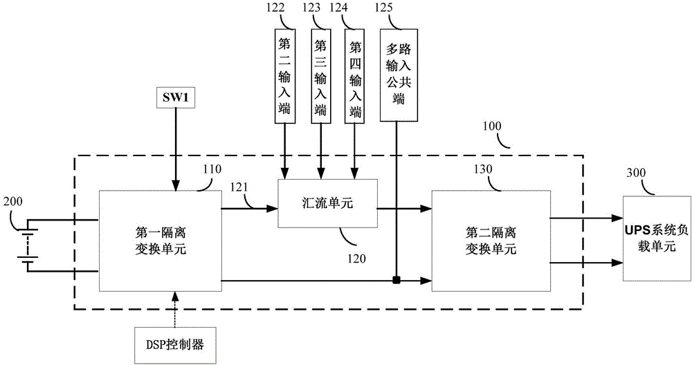
[0023] Such as image 3 As shown, the embodiment of the present invention provides a UPS cold start circuit 100 applied to an online UPS system. The UPS cold start circuit 100 is connected to a battery unit 200 and a UPS system load unit 300 . Wherein, the battery unit 100 is a DC power supply, which is a device for maintaining a stable current in the circuit, such as a dry cell, a storage battery and the like. The UPS system load unit 300 is the load for starting the UPS. The UPS cold start circuit 100 provides the starting voltage for the UPS system load unit 300 to enter the normal working state, thereby realizing the cold start function of the battery unit 200 for the UPS system. In the present invention, the UPS cold start circuit 100 includes: a first isolation transformation unit 110 , a confluence unit 120 , and a second isolation transformation unit 130 .
[0024] In the embodiment of the present invention, the input end of the first isolation transformation unit 110...
no. 2 example
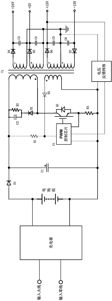
[0031] Such as Figure 4As shown, in the embodiment of the present invention, the first isolation conversion unit 110 is a flyback isolation converter. Specifically, in the flyback isolated converter: the anode of the diode D1 is connected to the positive pole of the battery unit, one end of the capacitor C1 is connected to the cathode of the diode D1, and the other end is connected to the negative pole of the battery unit, and the resistor R1 One end of the resistor R1 is connected to the cathode of the diode D1, the other end of the resistor R1 is connected to the cathode of the Zener diode ZD1, the anode of the Zener diode is connected to the battery unit, the capacitor C2 is connected in parallel with the Zener diode ZD1, and one end of the capacitor C3 is connected to the diode The cathode of D1 is connected, the other end of capacitor C3 is connected to the cathode of diode D2, the resistor R2 is connected in parallel with C3, one end of the primary side of the flyback i...
no. 3 example
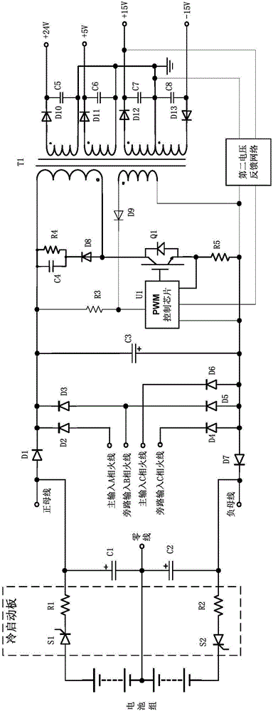
[0040] Such as Figure 5 As shown, in this embodiment of the present invention, different from the second embodiment, the first isolation conversion unit 110 in the embodiment of the present invention is a forward isolation converter.
[0041] In the embodiment of the present invention, the first isolation conversion unit 110 is composed of main parts such as a forward isolation transformer T1, a switch tube Q1, a PWM control chip U1, a diode D6, and a first voltage feedback network. Wherein, the input terminal of the first isolation conversion unit 110 is connected to the positive and negative poles of the battery unit 200, and the voltage of the battery unit 200 is chopped by the switching tube Q1 controlled by the PWM control chip U1, and then the first isolation conversion unit 110 outputs a certain voltage value The first DC voltage, such as 200V, is sent to the PWM control chip U1 of the first isolation conversion unit 110 after being processed by the first voltage feedb...
PUM
 Abstract
Description
Claims
Application Information
 - R&D
- Intellectual Property
- Life Sciences
- Materials
- Tech Scout
- Unparalleled Data Quality
- Higher Quality Content
- 60% Fewer Hallucinations
Browse by: Latest US Patents, China's latest patents, Technical Efficacy Thesaurus, Application Domain, Technology Topic, Popular Technical Reports.
© 2025 PatSnap. All rights reserved.Legal|Privacy policy|Modern Slavery Act Transparency Statement|Sitemap|About US| Contact US: help@patsnap.com


