Check patentability & draft patents in minutes with Patsnap Eureka AI!

DC step-down voltage regulator and pulse frequency modulation control circuit and method thereof

A technology of pulse frequency modulation and DC step-down, which is applied in the direction of converting DC power input to DC power output, adjusting electrical variables, and controlling/regulating systems, etc., and can solve problems such as not being able to optimize efficiency to the maximum extent

Pending Publication Date: 2017-03-22
BEIJING XIAOMI PINECONE ELECTRONICS CO LTD
View PDF7 Cites 0 Cited by
  • Summary
  • Abstract
  • Description
  • Claims
  • Application Information

AI Technical Summary

Problems solved by technology

[0006] The disadvantage of the above scheme is that the PSM control mode is actually an intermittent working mode of the PWM mode
In PSM mode, each module required for PWM work is enabled, so the efficiency cannot be maximized

Method used


Image

  • DC step-down voltage regulator and pulse frequency modulation control circuit and method thereof
  • DC step-down voltage regulator and pulse frequency modulation control circuit and method thereof
  • DC step-down voltage regulator and pulse frequency modulation control circuit and method thereof

Examples


Embodiment Construction

[0032] The specific implementation manners of the embodiments of the present disclosure will be described in detail below in conjunction with the accompanying drawings. It should be understood that the specific implementation manners described here are only used to illustrate and explain the embodiments of the present disclosure, and are not intended to limit the embodiments of the present disclosure.

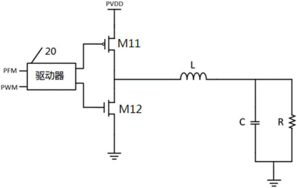
[0033] An embodiment of the present disclosure provides a pulse frequency modulation control circuit for a DC step-down voltage regulator, and the DC step-down voltage regulator includes an inductive element that supplies current to a load. figure 2 A schematic circuit diagram of a buck power switch tube driven by the DC step-down regulator and its passive control elements is shown. Such as figure 2 As shown, the PFM control signal obtained in the PFM mode passes through the driver 20 to control the on-off of the upper transistor M11 and the lower transistor M12 in the buck....


PUM


Abstract

The invention relates to a DC step-down voltage regulator and a pulse frequency modulation control circuit and method thereof, and belongs to the field of electronic circuits. The power consumption can be reduced. The circuit comprises a triangular wave generator, a sampling unit, a PFM control unit and a synchronization unit, wherein the triangular wave generator generates a triangular wave when an enable signal of the triangular wave generator is enabled; the sampling unit is used for sampling peak current of an inductive component and output voltage of the DC step-down voltage regulator; the PFM control unit controls the inductive component to be in a charged state when a first condition is met, and controls the inductive component to be in a follow current state when the peak current is greater than a default peak current threshold; the first condition is that two of the following three conditions are met and the remaining one is changed into a satisfied state from an unsatisfied state: the peak current is smaller than the default peak current threshold, the output voltage is lower than default reference voltage and a triangular wave charge-discharge cycle is completed; and the synchronization unit is used for synchronizing the moment when the enable signal of the triangular wave generator begins to be enabled and the moment when the inductive component begins to be charged.

Description

technical field [0001] Embodiments of the present disclosure relate to the field of electronic circuits, and in particular, to a DC step-down voltage stabilizer and a pulse frequency modulation control circuit and method thereof. Background technique [0002] With the demand for high current output of the system on chip and various modules of the mobile phone, the DC step-down regulator needs to have high efficiency under both light load and heavy load conditions. [0003] In order to improve efficiency at a light load, a more commonly used light load control mode is a Pulse Skip Modulation (PSM) control mode. The control principle of PSM current mode control mode is as follows: figure 1 As shown, the schematic diagram is for the buck of the DC step-down regulator, the upper transistor is PMOS, and the lower transistor is NMOS. It works as follows: [0004] The working loop of Pulse Width Modulation (PWM) mode is: the output voltage Vout of the buck passes through the fee...

Claims


Application Information

Patent Timeline
IPC IPC(8): H02M3/158
CPCH02M3/1584
Inventor 肖子剑
Owner BEIJING XIAOMI PINECONE ELECTRONICS CO LTD
Features
  • R&D
  • Intellectual Property
  • Life Sciences
  • Materials
  • Tech Scout
  • Unparalleled Data Quality
  • Higher Quality Content
  • 60% Fewer Hallucinations
Learn More