Switching joint of upper-layer concrete column and lower-layer concrete filled steel tubular column and implementation method

A technology of steel tube concrete columns and concrete columns, which is applied in the field of structural columns, can solve problems such as too dense steel bars, difficult control of construction quality, and insufficient safety reserves, so as to reduce the number and type of steel bars, easy control of construction quality, and improve safety reserve effect

Active Publication Date: 2017-03-29
大象建筑设计有限公司
View PDF6 Cites 9 Cited by
  • Summary
  • Abstract
  • Description
  • Claims
  • Application Information

AI Technical Summary

Problems solved by technology

[0005] 1. The structure is too complex, the construction is difficult, and the construction quality is difficult to control: in the core area of ​​the node, there are short ring-shaped steel bars and their spiral hoops connected to the steel pipe columns of the lower floor, vertical steel bars and encrypted stirrups of the upper concrete, and the concrete frame of the floor The existence of so many types of steel bars in the longitudinal steel bar of the beam, the U-shaped steel bar in the horizontal plus armpit ring, and the horizontal steel bar makes the number of steel bars in the core area too dense, which brings difficulties to the binding of steel bars and concrete pouring
The concrete frame beams on the upper floor have vertical and horizontal haunches in the joint core area, which brings difficulties to the erection of the formwork and the pouring of concrete
The above-mentioned construction difficulties caused by the complex structure will make it difficult to guarantee the quality of on-site construction
[0006] 2. The integrity of the connection between the core area of ​​the node and the steel pipe column of the lower layer is poor, which affects the reliability of the node: the concrete frame beam and concrete column of the upper layer transfer the upper load to the concrete filled steel pipe column of the lower layer through the connection between the core area of ​​the node and the steel pipe column of the lower layer column, so the connection between the core area of ​​the node and the steel pipe column of the lower layer is crucial
The current connection method happens to be the horizontal interface between two materials, steel and concrete, and the connection between the core area of ​​the node and the lower steel pipe column is completed only through the ring-shaped capping plate and the ring-shaped short steel bar. The integrity of the node is poor and Insufficient safety reserves are not conducive to the implementation of the requirements for strong columns and weak beams and strong joints and weak members for earthquake resistance of building structures
[0007] 3. The appearance of the joint is not ideal: the height of the core area of ​​the joint is equal to the anchorage length of the vertical reinforcement of the upper concrete column, so the height of the core area of ​​the joint is higher, and the vertical haunch of the corresponding beam end will also be higher. If it is due to the clear height As a result, the height of the suspended ceiling is not enough, which will cause the structural components of the node area to protrude from the ceiling, which will affect the appearance of the node area and the clear height of the building

Method used


Image

  • Switching joint of upper-layer concrete column and lower-layer concrete filled steel tubular column and implementation method
  • Switching joint of upper-layer concrete column and lower-layer concrete filled steel tubular column and implementation method
  • Switching joint of upper-layer concrete column and lower-layer concrete filled steel tubular column and implementation method

Examples


Embodiment 1

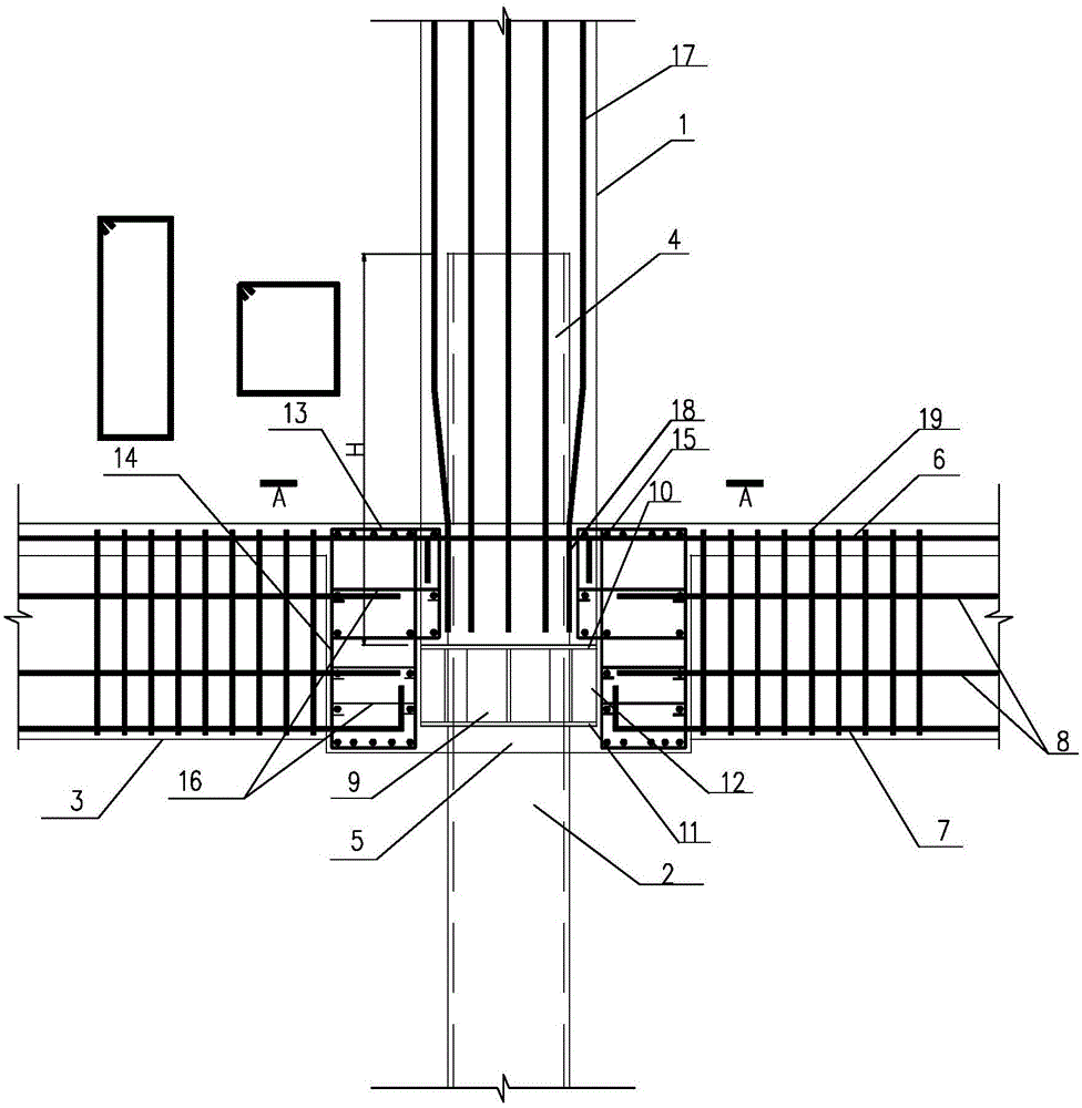
[0039] Such as figure 1 , figure 2As shown, the node is the junction of the upper concrete column 1 and the lower concrete-filled steel tube column 2, and the node area is located at the conversion position of the structural columns of different forms on the upper and lower floors of the building.

[0040] it includes:

[0041] Concrete-filled steel tube column 2 on the lower floor, concrete column 1 on the upper floor, and concrete beam 3, the diameter of the concrete column 1 on the upper floor is larger than that of the concrete-filled steel pipe column 2, and the floor beam is a concrete beam 3;

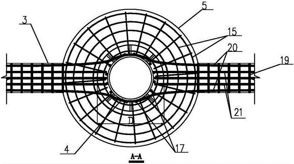
[0042] The concrete ring beam 5 wraps the entire node core area, the concrete beam 3 on the floor is connected to the concrete ring beam 5, and the longitudinal reinforcement of the concrete beam 3 is anchored into the concrete ring beam 5;

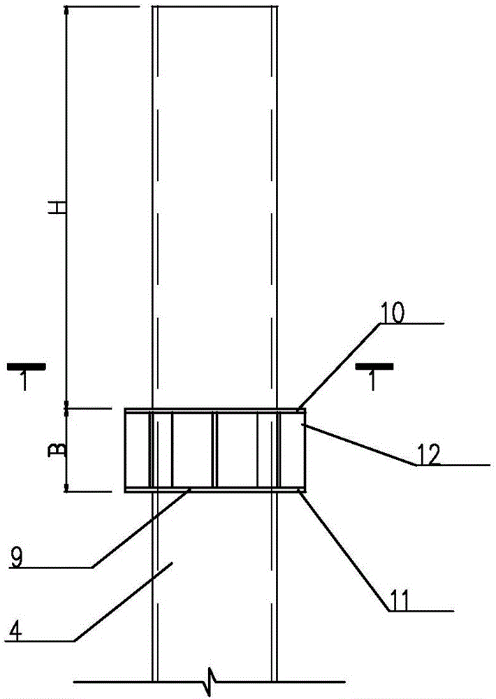
[0043] Such as image 3 As shown, the annular corbel 9 includes an upper ring plate 10, a lower ring plate 11, and a reinforcing rib 12...

Embodiment 2

[0051] Such as Figure 3-Figure 11 As shown, the conversion method of the joints of the upper large-diameter concrete column and the lower small-diameter steel pipe concrete column, the method includes the following steps:

[0052] 1 as image 3 , as shown in 4, the ring-shaped corbel is welded on the upper part of the steel pipe column. The annular corbel 9 is composed of an upper ring plate 10 , a lower ring plate 11 and a reinforcing rib 12 . The thickness of the steel plate of the annular corbel 9 is the same as the wall thickness of the steel pipe column 4, and the height B of the annular corbel 9 is calculated based on the difference in vertical force bearing capacity generated by the area difference between the upper concrete column 1 and the lower concrete filled steel pipe column 2. The diameter D of the annular corbel 9 is the same as that of the upper concrete column 1 . The elevation of the lower ring plate 11 of the annular corbel 9 is the same as that of the b...


PUM


Abstract

The invention provides a switching joint of an upper-layer concrete column and a lower-layer concrete filled steel tubular column. The joint is a connecting point of the upper-layer concrete column and the lower-layer concrete filled steel tubular column, the concrete filled steel tubular column upwards extends into the concrete column, a concrete ring beam is connected to the concrete column in a surrounding manner, a vertical reinforcement in the concrete column is anchored into the concrete ring beam, and an annular bracket is welded to the outer wall of the concrete filled steel tubular column. The invention further provides a switching method of the joint. The annular bracket provided in the switching joint simplifies construction of the switching structure, the construction difficulty is reduced, and the construction quality is easy to control. Meanwhile, the lower-layer concrete filled steel tubular column directly extends upwards into the upper-layer concrete column, the vertical reinforcement of the upper-layer concrete column is directly welded to the concrete filled steel tubular column in a joint core zone, the joint integrity is strengthened through wrapping of the concrete ring beam to the joint zone, safety storage of the switching joint is improved, and the requirements for strong columns and weak beams and strong joints and weak components in the building stricture seismic design are shown; and in addition, the appearance effect is good.

Description

technical field [0001] The invention relates to a structural column, in particular to a conversion node in which the upper layer is a concrete column and the lower layer is a steel pipe concrete column, and also relates to an implementation method of the node. Background technique [0002] In some reinforced concrete buildings, the structural columns in the common spaces of the ground floor or lower floors are designed as smaller diameter concrete filled steel tube columns. This design enhances the modernity of the building and improves the transparency and visual effect of the large public space. However, in order to save costs or due to the requirements of the building appearance, the beams and columns of the upper floor of the steel tube concrete columns are still concrete structures, especially due to the Because of the force, the diameter of the upper concrete column is often larger than the diameter of the lower concrete-filled steel pipe column, forming an unfavorable...

Claims


Application Information

Patent Timeline
Patent Type & Authority Applications(China)
IPC IPC(8): E04B1/30E04B1/58
CPCE04B1/30E04B1/58
Inventor 胡凌华龚铭包风赵亮亮
Owner 大象建筑设计有限公司
Why Eureka
Try Eureka