Distribution valve and conveying pump adopting same

A technology of distributing valves and conveying pumps, which is applied to components, pumps, and pump components of pumping devices for elastic fluids, and can solve problems such as difficult suction, low volumetric efficiency, and low pumping pressure, and meet the requirements of high lift and long-distance pipeline transportation, improve volumetric efficiency, and prevent material backflow

Active Publication Date: 2017-03-29
山东瀚纶环保机械有限公司
View PDF6 Cites 2 Cited by
  • Summary
  • Abstract
  • Description
  • Claims
  • Application Information

AI Technical Summary

Problems solved by technology

[0003] 1. For S-pipe valve delivery pumps, C-shaped pipe valve delivery pumps, and skirt valve delivery pumps, material backflow will occur during the reversing process of the two-cylinder pumping, thereby reducing the delivery efficiency. The longer the delivery distance, the higher the delivery height. The higher the pressure, the greater the conveying pressure, the more serious the material backflow, and the lower the conveying efficiency
[0004] 2. For the gate valve delivery pump, due to the poor sealing performance of the gate valve and no wear compensation mechanism, the pumping pressure is low, the delivery distance is short, and the delivery height is low
[0005] 3. For the above-mentioned various types of delivery pumps, since there is only one suction port, when transporting materials with poor fluidity, the material flow resistance is large and suction is difficult, resulting in low volumetric efficiency

Method used


Image

  • Distribution valve and conveying pump adopting same
  • Distribution valve and conveying pump adopting same
  • Distribution valve and conveying pump adopting same

Examples


Embodiment 1

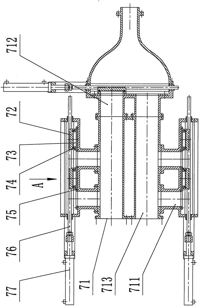
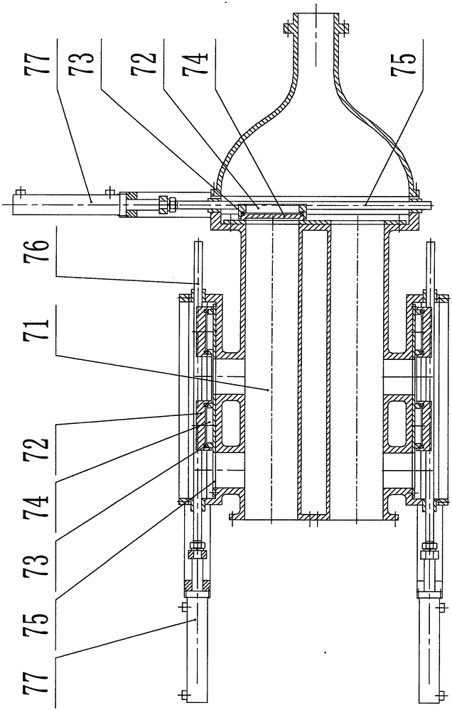
[0044] see figure 1 and figure 2 , which shows a schematic diagram of a dispensing valve according to a preferred embodiment of the present invention. The distribution valve includes: distribution valve box 71, sliding body 72, elastic seal 73, sliding seal 74, friction plate 75, guide rod 76, driving device 77, distribution valve body 1 711, distribution valve body 2 712, distribution valve Body III 713.

[0045] Distribution valve box 71 is a split structure composed of multiple parts, including distribution valve body 1 711, distribution valve body 2 712, distribution valve body 3 713, distribution valve body 1 711, distribution valve body 2 712 and distribution valve body Three 713 are fixedly connected together.

[0046] The distributing valve includes two feed valves and a discharge valve, both of which are slide valve structures, and each feed valve includes two valve plate units and two feed ports, so The discharge valve described above includes a valve plate unit...

Embodiment 2

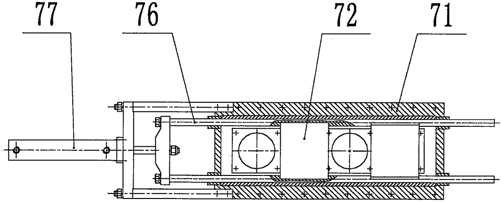
[0051] see image 3, which shows a schematic diagram of a dispensing valve according to another preferred embodiment of the present invention. The distribution valve includes: a distribution valve box 71 , a sliding body 72 , an elastic seal 73 , a sliding seal 74 , a friction plate 75 , a guide rod 76 , and a driving device 77 .

[0052] The driving device 77, the guide rod 76 and the friction plate 75 are installed on the distribution valve box 71, the power output end of the driving device 77 is connected with the guide rod 76, and the guide rod 76 is connected with the sliding body 72 again, and the sliding seal 74 and the elastic The sealing member 73 is installed on the sliding body 72, and the elastic sealing member 73 is located between the sliding body 72 and the sliding sealing member 74, the friction plate 75 is located between the distribution valve box 71 and the sliding sealing member 74, the elastic force of the elastic sealing member 73 Under action, the slidi...

Embodiment 3

[0056] see Figure 4 , which shows a schematic diagram of a dispensing valve according to another preferred embodiment of the present invention. The distributing valve includes: a distributing valve box 71 , a sliding body 72 , an elastic seal 73 , a sliding seal 74 , a driving device 77 , and a seat valve head 78 .

[0057] The distribution valve is a mixed structure of a slide valve and a seat valve, and the distribution valve includes two inlet valves and two outlet valves. The feed valve is a slide valve structure, wherein the driving device 77 is connected with the sliding body 72, the sliding seal 74 and the elastic seal 73 are installed on the distribution valve box 71, and the elastic seal 73 is located between the sliding seal 74 and the distribution valve box Between 71, there are through holes on the sliding body 72 and the sliding sealing member 74, and the sliding sealing member 74 can be compressed on the sliding body 72 under the action of the elastic sealing m...


PUM


Abstract

The invention discloses a distribution valve which comprises a distribution valve box, a slide body, an elastic sealing part, a slide sealing part, a friction plate, a guide rod and a drive device, wherein the drive device, the guide rod and the friction plate are mounted on the distribution valve box; the drive device is connected with the guide rod; the guide rod is connected with the slide body; the slide sealing part and the elastic sealing part are mounted on the slide body; the elastic sealing part is positioned between the slide sealing part and the slide body; the drive device drives the guide rod; and the guide rod, the slide body, the elastic sealing part and the slide sealing part move on the friction plate, so that opening-closing and reversing of a valve are realized. The distribution valve has the advantages of being reliable in sealing, great in conveying pressure, small in material absorbing resistance, high in capacity efficiency and the like. The invention further discloses a conveying pump adopting the distribution valve.

Description

technical field [0001] The present invention generally relates to the field of pumping equipment, in particular to a distributing valve used in pipeline transportation of slurry, paste and paste-like materials and a delivery pump using the distributing valve. Background technique [0002] Ball valve delivery pumps, seat valve delivery pumps, gate valve delivery pumps, S-pipe valve delivery pumps, C-shaped pipe valve delivery pumps, skirt valve delivery pumps and other reciprocating delivery pumps are mainly used for pumping slurry, paste and similar paste, etc. Materials, such as drilling fluid, fracturing fluid, mud, concrete, coal slime, municipal sludge, printing and dyeing sludge, chemical sludge, liquid food raw materials, etc. Above existing reciprocating delivery pump mainly has following shortcoming and deficiency: [0003] 1. For S-pipe valve delivery pumps, C-shaped pipe valve delivery pumps, and skirt valve delivery pumps, material backflow will occur during the ...

Claims


Application Information

Patent Timeline
Patent Type & Authority Applications(China)
IPC IPC(8): F04B53/10F04B15/02
CPCF04B15/02F04B53/10
Inventor 巩高铄
Owner 山东瀚纶环保机械有限公司
Why Eureka
Try Eureka