Microbial sensor based on turbidity detection and turbidity detection method

A microbial sensor and detector technology, applied in the field of biomedicine, food inspection, and biochemical analysis, can solve problems such as false positives and large test errors

Inactive Publication Date: 2017-03-29
黄辉 +2
View PDF14 Cites 3 Cited by
  • Summary
  • Abstract
  • Description
  • Claims
  • Application Information

AI Technical Summary

Problems solved by technology

However, these methods are indirect tests (such as testing the metabolites of microorganisms), rather than direct observation of microorganisms, so there are shortcomings such as large test errors and false positives.

Method used


Image

  • Microbial sensor based on turbidity detection and turbidity detection method

Examples


Embodiment 1

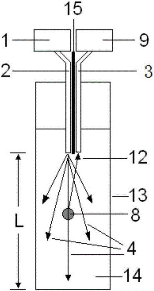
[0025] see figure 1 As shown, the present embodiment provides a microbial sensor based on turbidity detection, comprising a light source 1, a first optical fiber 2 and a second optical fiber 3 composed of two optical fibers side by side, an optical isolation layer 15, a detector 9, and a in the cuvette 13 where the liquid medium 14 is placed. The excitation light 4 emitted by the light source passes through the first optical fiber 2 and irradiates the particles 8 in the culture medium 14 . After being scattered by the particles 8 , the scattered light 12 is received by the second optical fiber 3 and transmitted to the detector 9 .

[0026] The optical isolation layer 15 between the optical fibers can separate the light beams in the first optical fiber 2 and the second optical fiber 3 (ie, separate excitation light and scattered light) to avoid mutual interference. At the same time, since the excitation light emitted by the first fiber is divergent, the light intensity is the ...

Embodiment 2

[0032] The difference between this embodiment and Embodiment 1 is that the optical fiber is replaced with a metal capillary. This embodiment only describes the structure different from the embodiment, and the same parts will not be repeated. In this embodiment, a first metal capillary tube and a second metal capillary tube are used to replace the first optical fiber 2 and the second optical fiber 3 to transmit probe light and collect scattered light. Since the light beam is transmitted inside the metal capillary, the side wall of the capillary can effectively reflect the light beam, so the side wall of the capillary can isolate the probe light and scattered light; at this time, there is no need to use an optical isolation layer between the two capillaries. The implementation of this embodiment can achieve the same technical effect as the first embodiment.


PUM

PropertyMeasurementUnit
thicknessaaaaaaaaaa
thicknessaaaaaaaaaa
thicknessaaaaaaaaaa

Abstract

The invention relates to a microbial sensor based on turbidity detection and a turbidity detection method. The microbial sensor based on the turbidity detection comprises a light source, a first light guiding device, a second light guiding device, a detector and a container used for placing an object to be detected, wherein exciting light emitted by the light source passes through the first light guiding device, then passes through the object to be detected, is received by the second light guiding device and finally is transmitted to enter the detector. The microbial sensor provided by the invention has the beneficial effects that compared with 90-degree scattered light detection in the traditional turbidity detection, two side-by-side light guiding devices are adopted for detecting scattered light, and the characteristics of concentrated light intensity, high receiving sensitivity and strong anti-jamming capability are realized; compared with the traditional colony counting method, luminous power values received by the light guiding devices are of comprehensive response on all the microorganisms in light spot areas of the exciting light, so that the advantage of rapid detection is realized; and compared with other rapid detection methods, a colony is directly detected, thereby being more intuitive and reliable.

Description

technical field [0001] The invention relates to a turbidity detection-based microbial sensor and a turbidity detection method, which can be applied to the fields of biochemical analysis, biomedicine, food inspection and the like. Background technique [0002] Turbidity detection (ie, detection of suspended particulate matter) based on light scattering effect is one of the commonly used methods in biochemical analysis. Scattering deflects the propagation direction of the beam (the angle of deflection is referred to as the "scattering angle"), and the scattered light is typically detected using a 90-degree scattering angle (ie, the direction perpendicular to the incident light), thereby separating the scattered light from the transmitted light. However, the scattering angle is distributed between 0 and 360 degrees, and the 90-degree detection can only collect a small part of the scattered light, and the detection efficiency is low. etc.); and, the scattered light is very weak...

Claims


Application Information

Patent Timeline
Patent Type & Authority Applications(China)
IPC IPC(8): G01N21/51
CPCG01N21/51
Inventor 黄辉渠波李雪晶张骥白敏
Owner 黄辉
Why Eureka
Try Eureka