
Integrated three-phase all-fiber optical current transformer

A current transformer and all-fiber technology, which is applied in the direction of voltage/current isolation, etc., can solve the problems that affect the application and promotion of all-fiber current transformers, the light source light wavelength changes with temperature, and the small current measurement accuracy is poor, so as to improve the small current. Improve measurement accuracy, improve the accuracy and reliability of full temperature measurement, and realize the effect of automatic optical path compensation

Inactive Publication Date: 2017-03-29
长园深瑞继保自动化有限公司
View PDF7 Cites 3 Cited by
  • Summary
  • Abstract
  • Description
  • Claims
  • Application Information

AI Technical Summary

Problems solved by technology

[0005] The optical fiber current transformer of the prior art has exposed many problems in the actual application process: the luminous wavelength of the light source changes with the temperature, the output optical power is unstable, the measurement accuracy of the optical fiber current transformer changes with the external environment temperature, and the small current measurement accuracy Poor and poor operation reliability have adverse effects on protection applications, which may lead to smart substation relay protection blocking and reaching the protection action threshold, which affects the application and promotion of all-fiber-optic current transformers

Method used


Image

  • Integrated three-phase all-fiber optical current transformer
  • Integrated three-phase all-fiber optical current transformer
  • Integrated three-phase all-fiber optical current transformer

Examples


Embodiment Construction

[0025] The present invention will be described in further detail below in conjunction with the accompanying drawings and embodiments. The three-phase integrated all-fiber optic current transformer (transformer) of the present invention is based on the Ampere loop law and the Faraday magneto-optical effect, and carries out current measurement to the A, B, C phase primary current-carrying conductors of the line interval of the intelligent substation, through The current value on the primary current-carrying conductor is indirectly measured by detecting the optical path difference formed between the two beams of polarized light transmitted in the optical fiber arranged around the primary current-carrying conductor.

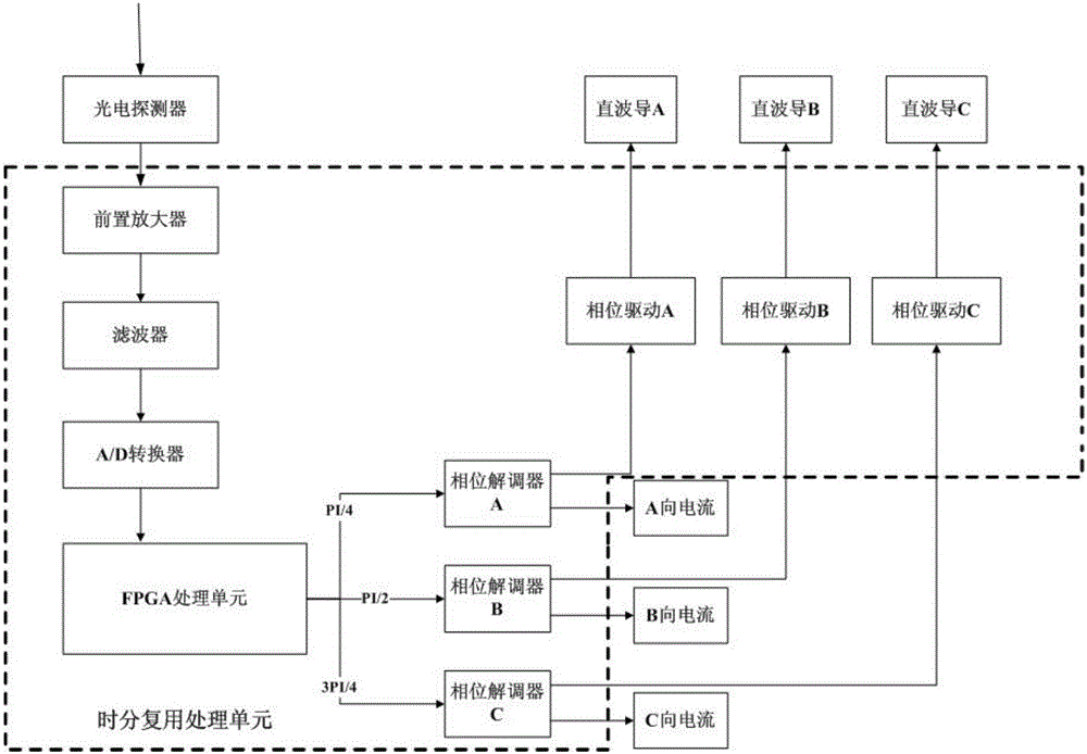
[0026] Such as figure 1 As shown, the three-phase integrated all-fiber-optic current transformer of the present invention is composed of an optical system unit and a digital signal processing unit (time-division multiplexing processing unit).

[0027] The optical sy...


PUM

PropertyMeasurementUnit
Elastic modulusaaaaaaaaaa

Abstract

The invention discloses an integrated three-phase all-fiber optical current transformer and solves a technical problem of how to improve all-temperature measurement precision and integration reliability. The integrated three-phase all-fiber optical current transformer comprises a light path system unit and a digital signal processing unit, wherein a light source, a polarization-maintaining coupler, a polarizer, a straight waveguide, a delay fiber and a sensing ring of the light path system unit are sequentially connected, the digital signal processing unit is provided with a light source intensity noise inhibition unit, a signal processing unit, a phase demodulator and a phase driving circuit which are sequentially connected, and the phase driving circuit is connected with the straight waveguide. Compared with the prior art, intensity noise is inhibited through a dual-polarized light path, all-temperature measurement precision and small current measurement precision of the current transformer are improved, a time division multiplexing circuit is employed by the signal processing unit, optical devices and the sensing ring of the light path system are simplified, phase time delay of the sensing ring is precisely controlled, automatic light path compensation is realized, curing manufacturing of the sensing ring is realized, and all-temperature measurement precision and reliability of the all-fiber optical current transformer are improved.

Description

technical field [0001] The invention relates to a power primary equipment, in particular to an integrated all-optical fiber current transformer. Background technique [0002] The construction of smart grid is one of the seven strategic emerging industries to be cultivated in my country's "13th Five-Year Plan". Digital substation is the main component of smart grid. In the State Grid's "Building a Strong Smart Grid" plan, a "five vertical and six horizontal" UHV transmission backbone grid will be formed in 2020, and a strong smart grid will be built in an all-round way, so that the resource allocation capability, security level, and operation of the grid will be improved. Efficiency and user interaction are significantly improved. [0003] The all-fiber-optic current transformer is based on Ampere's loop law and Faraday's magneto-optic effect for current measurement, by detecting the phase difference formed between the two beams of polarized light transmitted in the optical...

Claims


Application Information

Patent Timeline
IPC IPC(8): G01R15/24
CPCG01R15/24
Inventor 徐盛果陈锐刘永峰龚戈峰
Owner 长园深瑞继保自动化有限公司
Learn More