Method and device for suppressing light source intensity noise by using proportional compensation of electro-optical modulator

An electro-optical modulator and light source intensity technology, which is applied in the exploration of optical devices and other directions, can solve the problems of low response bandwidth, limitation, and limited noise suppression effect of low-frequency intensity noise of acousto-optic modulators, and achieves easy application and implementation, low cost, and realization of Effects of Intensity Noise Suppression

Active Publication Date: 2022-06-21
ZHEJIANG LAB +1
View PDF17 Cites 0 Cited by
  • Summary
  • Abstract
  • Description
  • Claims
  • Application Information

AI Technical Summary

Problems solved by technology

The pattern cleaner method has obvious suppression effect on intensity noise, but has limited suppression effect on low-frequency intensity noise
The semiconductor optical amplifier saturation suppression method uses the gain saturation characteristics of the optical amplifier to suppress the light source intensity noise, but it cannot meet the high-power input requirements of the optical trap sensing system due to the limitation of the input optical power of the amplifier.
The traditional optoelectronic feedback method is to sample the output optical signal and feed it back to the acousto-optic modulator or electro-optic modulator to adjust the optical power to achieve the effect of noise suppression, but the response bandwidth of the acousto-optic modulator is low, and the optical power of the electro-optic modulator The power damage threshold is low, which is limited in the application of optical trap sensing systems

Method used


Image

  • Method and device for suppressing light source intensity noise by using proportional compensation of electro-optical modulator
  • Method and device for suppressing light source intensity noise by using proportional compensation of electro-optical modulator
  • Method and device for suppressing light source intensity noise by using proportional compensation of electro-optical modulator

Examples


Embodiment

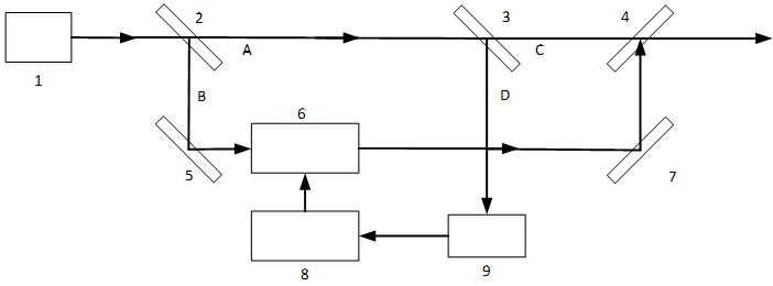
[0025] refer to figure 1 , a device for suppressing light source intensity noise using electro-optical modulator proportional compensation, comprising a light source 1, a first beam splitter 2, a second beam splitter 3, a beam combiner 4, a first reflector 5, an electro-optic modulator 6, a second reflector Mirror 7 , signal processing module 8 and photodetector 9 . The light emitted by the light source 1 is divided into a beam A and a beam B by the first beam splitter. The beam A is stronger than the beam B. The beam B enters the electro-optic modulator 6 through the first reflector 5, and the beam A is divided into beams by the second beam splitter 3. C and D, the light beam C is stronger than the light beam D, the light beam D is connected to the photodetector 9, the electrical signal after photoelectric conversion is connected to the signal processing module 8, and the signal processing module 8 outputs the electrical signal to control the electro-optical modulator 6, and ...


PUM


Abstract

The invention discloses a method and a device for suppressing light source intensity noise by using electro-optical modulator proportional compensation. Use the optical beam splitting device to split the output of the light source in proportion to form a pair of high-power and low-power beams, sample the high-power beams to obtain light intensity fluctuation information, and load the modulated signal to the electro-optic modulator through the signal processing module. The light intensity fluctuation of the low-power beam is modulated to generate an optical signal with the same intensity as the high-power beam and a phase difference of 180 degrees, and finally combined with the high-power beam for output, thereby achieving the effect of suppressing the fluctuation of the output light intensity. The invention overcomes the shortcoming of the low power threshold of the electro-optic modulator, realizes the suppression of the intensity noise of the high-power laser, has low cost, and is easy to apply and implement.

Description

technical field [0001] The present invention relates to a method and device for reducing light source intensity noise, in particular to a method and device for reducing light source intensity noise by compensating for light intensity fluctuation using an electro-optical modulator. Background technique [0002] According to the theory of photoelectric detection, when the photodetector receives the optical signal input and converts the electrical signal output, there are mainly two noise sources. One is the shot noise of the photodetector. Due to the particle properties of light, even if the average intensity of the incident light remains unchanged, the number of electrons emitted by the detector fluctuates randomly around a statistical average. The shot noise power spectral density is proportional to the light source power P, as follows: [0003] [0004] In the formula, is the average optical power of the incident light, h is Planck's constant, c is the speed of lig...

Claims


Application Information

Patent Timeline
Patent Type & Authority Patents(China)
IPC IPC(8): G01V8/10
CPCG01V8/10
Inventor 高晓文陈杏藩傅振海付盼李楠胡慧珠刘承
Owner ZHEJIANG LAB
Why Eureka
Try Eureka