
Attosecond precision timing detection device and method based on linear optical effect

An optical effect, timing detection technology, applied in the field of ultrafast optics, can solve problems such as expensive cost, complex experimental setup, can not provide timing resolution, etc., to achieve the effect of low cost, easy integration and easy installation

Active Publication Date: 2022-07-01
TIANJIN UNIV
View PDF4 Cites 0 Cited by
  • Summary
  • Abstract
  • Description
  • Claims
  • Application Information

AI Technical Summary

Problems solved by technology

However, since the BOC scheme is based on nonlinear optical effects, it usually cannot provide sufficient timing resolution when the input average optical power is below 1 mW
Recently, a linear timing detection scheme based on heterodyne technology has been reported, which has the potential to work at lower optical power levels, but at the expense of more expensive cost and complex experimental setup compared to the BOC scheme
Therefore, until now, there is no simple and reliable timing detector capable of operating at low input optical power

Method used


Image

  • Attosecond precision timing detection device and method based on linear optical effect
  • Attosecond precision timing detection device and method based on linear optical effect
  • Attosecond precision timing detection device and method based on linear optical effect

Examples


Embodiment Construction

[0035] The present invention will be further described in detail below with reference to the accompanying drawings and specific embodiments. It should be understood that the specific embodiments described herein are only used to explain the present invention, but not to limit the present invention.

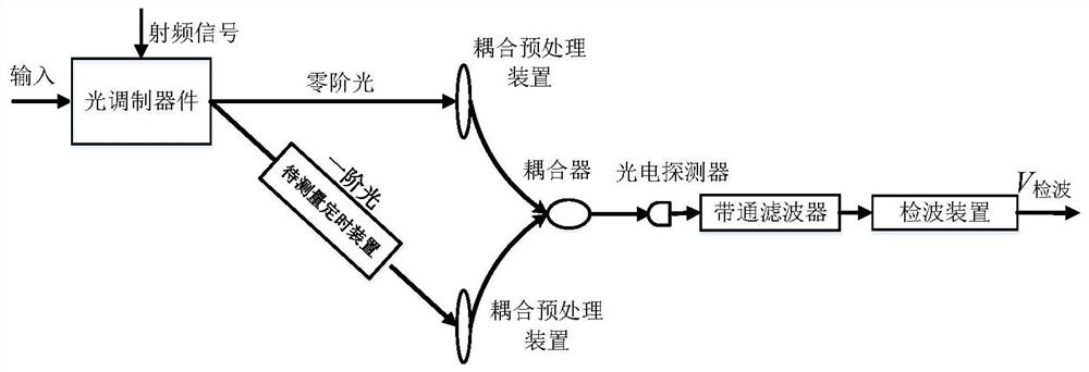
[0036]The schematic diagram of the timing detection method based on linear optical effects is shown in the figure. figure 1 As shown, the timing detection system is composed of an optical modulation device, a timing device to be measured, a coupling preprocessing device, an optical fiber coupler, a photodetector, a band-pass filter, and a detection device. The light modulation device is an acousto-optic modulator. The optical modulation device takes the incident optical signal as the modulated signal, and is driven by the radio frequency signal to output the optical signal to obtain the frequency offset of the radio frequency modulation signal. The coupling preprocessing device ...


PUM


Abstract

The invention discloses an attosecond precision timing detection device and method based on a linear optical effect. The method is as follows: introducing a radio frequency offset frequency into an optical pulse signal of input light, and introducing a to-be-measured optical pulse signal into the optical pulse signal with the introduced radio frequency offset frequency. Timing error; the original optical pulse signal and the optical pulse signal introduced with timing error are coupled to each other; the optical pulse signal output after coupling is converted into an electrical signal, which is expressed as an electrical pulse sequence in the time domain, and the electrical pulse sequence includes the radio frequency offset. Shift the frequency signal, extract the RF offset frequency signal through a band-pass filter; extract the envelope signal of the RF offset frequency signal, the envelope signal contains the timing information to be measured; record the envelope signal under different delays in real time The voltage value can obtain the relationship curve between the timing information introduced by the timing device to be measured and the final output voltage of the detection device of the present invention, thereby completing the process of timing calibration.

Description

technical field [0001] The invention relates to the technical field of ultrafast optics, in particular to an attosecond precision timing detection method and a balancing device based on a linear optical effect. Background technique [0002] High-accuracy timing detection devices are regarded as key components in many cutting-edge applications. For example, in next-generation photonic science projects such as X-ray free electron lasers (XFELs), timing stabilization and distribution of fiber-optic links, long-range laser / microwave synchronization, and pump detection to achieve scientific goals of subatomic spatiotemporal resolution Experiments all require high-precision timing detection. In addition, high-precision timing detection has recently played a key role in large astronomical telescope arrays, strain sensing, movable optical clocks, time-of-flight detection, coherent synthesis of high-power pulses, synthesis of ultrashort optical pulses, and soliton characterization. ...

Claims


Application Information

Patent Timeline
Patent Type & Authority Patents(China)
IPC IPC(8): G01J11/00
CPCG01J11/00
Inventor 辛明弗朗茨·卡特纳凯末尔·沙法克王童
Owner TIANJIN UNIV
Learn More