FPGA clock network design

A clock network, clock technology, applied in computing, special data processing applications, instruments, etc., can solve problems such as complex circuit design

Inactive Publication Date: 2017-03-29
马云利
View PDF0 Cites 4 Cited by
  • Summary
  • Abstract
  • Description
  • Claims
  • Application Information

AI Technical Summary

Problems solved by technology

In addition, the current circuit design is becoming more and more complex, and the design requirements for the clock are also getting higher and higher. In order to meet their own needs, the clock system is ever-changing

Method used


Image

  • FPGA clock network design
  • FPGA clock network design
  • FPGA clock network design

Examples


Embodiment Construction

[0011] The present invention will be described in detail below in conjunction with the accompanying drawings and examples.

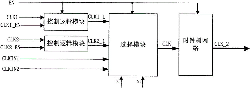
[0012] figure 1 As shown, the architecture of the clock network is designed. Since the clock signal runs through the entire chip, when the chip is working, the clock signal jumps periodically at the clock input end of the storage unit, and the driven load capacitance is very large, resulting in large power consumption. With the help of the global control signal EN, the clock is turned off when the programmable logic device is in the programming state or in the sleep mode to reduce dynamic power consumption. The user divides the frequency of the external clock CLK1 and CLK2 by programming to obtain the internal clock CLKIN1 and CLKIN2 of the desired frequency. After the external clock passes through the gate control circuit and the adjustment circuit of the conversion time, the selection module selects the clock channel with the internal clock. The select...


PUM


Abstract

The invention puts forwards a scheme for FPGA clock network design for a programmable logic device. In order to meet the requirement for timing sequences by obtaining smaller clock skew, a design scheme for netted trees is adopted for the clock network. Clock burrs can be eliminated by filtration due to a push-pull structure added to a leaf unit. Noise interference caused by coupling and parasitic effect is eliminated so that stable waves are generated. In addition, configurable design is carried out on the clock network and is compatible to ordinary programmable devices.

Description

technical field [0001] With the continuous improvement of people's requirements for high-speed clocks, the design requirements of clock networks have become more and more stringent, and the quality of clock trees has become the key to the design of clock networks. This article introduces the basic concept of clock tree and gives a clock network design scheme in programmable logic devices. Balancing propagation delays through a clock tree results in less clock skew, which reduces its impact on setup and hold times. The push-pull structure is adopted in the leaf unit of the clock tree, which has the function of deburring, eliminates the interference of coupling noise, and ensures the reliability of the clock. In addition, the clock network of the device has programmable capability, has good flexibility, and is universal for general programmable logic devices. Background technique [0002] With the rapid development of the manufacturing process, the chip size is shrinking and...

Claims


Application Information

Patent Timeline
Patent Type & Authority Applications(China)
IPC IPC(8): G06F17/50
Inventor 马云利
Owner 马云利
Why Eureka
Try Eureka