
Vibration mobile mechanism based on smart material driving, and preparation method of the same

A mobile mechanism and smart material technology, which can be used in motor vehicles, transportation and packaging, etc., can solve the problems of complex structure and cumbersome manufacturing process of micro and small mobile mechanisms, and achieve the effects of light weight, flexible movement and easy forming.

Active Publication Date: 2017-04-19
XI AN JIAOTONG UNIV
View PDF5 Cites 7 Cited by
  • Summary
  • Abstract
  • Description
  • Claims
  • Application Information

AI Technical Summary

Problems solved by technology

[0003] The purpose of the present invention is to provide a vibrating moving mechanism driven by intelligent materials and its preparation method, so as to solve the shortcomings of the existing micro-moving mechanism with complex structure and cumbersome manufacturing process

Method used


Image

  • Vibration mobile mechanism based on smart material driving, and preparation method of the same
  • Vibration mobile mechanism based on smart material driving, and preparation method of the same
  • Vibration mobile mechanism based on smart material driving, and preparation method of the same

Examples


specific Embodiment approach 1

[0029] Specific implementation method 1: After the biased sinusoidal signal is amplified by a high-voltage amplifier, it is connected to the copper foil electrode of the moving mechanism coated with a circular or elongated carbon paste electrode. When the frequency of the input signal reaches the resonance frequency of the mechanism, it can be realized Institutional movement.

specific Embodiment approach 2

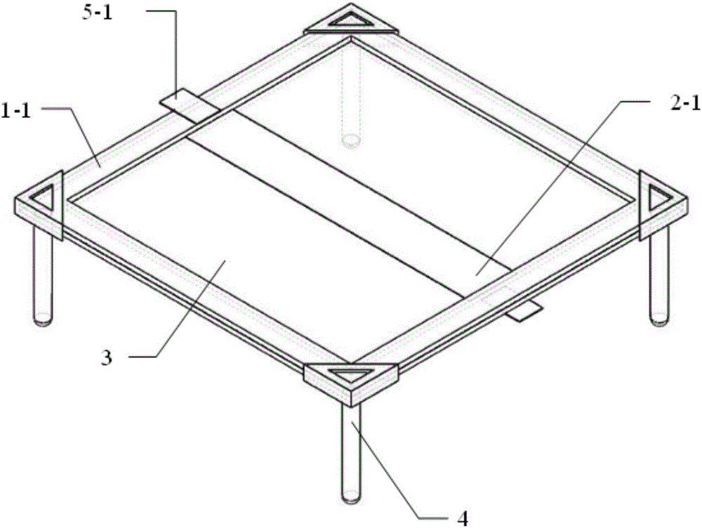
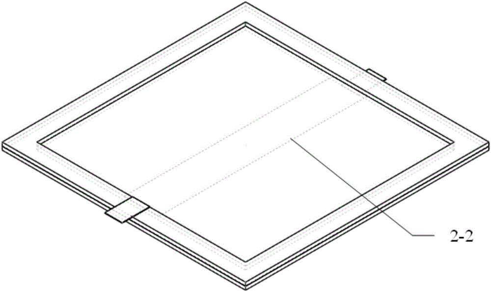
[0030] Embodiment 2: After the triangular wave signal is amplified by a high-voltage amplifier, it is connected to the copper foil electrode of the moving mechanism coated with circular or strip-shaped carbon paste electrodes. When the frequency of the input signal reaches the resonance frequency of the mechanism, the movement of the mechanism can be realized. .

[0031] The present invention is a vibrating moving mechanism based on intelligent materials. The core driving part adopts VHB 4910 adhesive tape of 3M Company, which is biaxially pre-stretched, pasted up and down with a plexiglass frame for displacement constraint, and then evenly coated with liquid carbon paste on its upper and lower surfaces. The electrodes form a sandwich structure. Copper foil electrodes are pasted on the plexiglass frame and contacted with the upper and lower carbon paste electrodes, and a kilovolt-level high voltage is applied. Under the action of Maxwell stress, the VHB will deform in the thick...


PUM


Abstract

The invention discloses a vibration mobile mechanism based on smart material driving, and a preparation method of the same. The vibration mobile mechanism based on smart material driving includes a driver and support feet, wherein the driver includes dielectric elastomer material, an upper framework and a lower framework; the dielectric elastomer material is clamped between the upper framework and the lower framework; the upper framework and the lower framework are fixed on the plurality of support feet; an upper surface copper foil electrode is arranged on the upper framework; a lower surface copper foil electrode is arranged on the lower framework; the upper surface copper foil electrode and the lower surface copper foil electrode are arranged at the opposite two sides of the vibration mobile mechanism; the upper surface of the dielectric elastomer material is coated with an upper surface carbon paste electrode which is electrically connected with the upper surface copper foil electrode; and the lower surface of the dielectric elastomer material is coated with a lower surface carbon paste electrode which is electrically connected with the lower surface copper foil electrode. The vibration mobile mechanism based on smart material driving utilizes the dielectric elastomer smart material as the driving core, has the advantages of being simple in structure, being light in weight and being high in motion resolution, and has greater application potential in the industrial detection field, the micro-electro-mechanical system assembling field, the optical engineering field and the like.

Description

technical field [0001] The invention belongs to the field of miniature motion mechanisms, in particular to a vibrating movement mechanism and a preparation method thereof. Background technique [0002] Due to its small size and flexible maneuverability, the micro motion mechanism has great application potential in the fields of industrial inspection, micro-electro-mechanical system assembly, and optical engineering. Existing micro-moving mechanisms are mainly divided into wheel-type moving mechanisms, inchworm-type moving mechanisms, inertial friction-type moving mechanisms, and resonance-type moving mechanisms. The wheel-type moving mechanisms move faster, but their motion resolution is low. Inchworm and inertial friction-based moving mechanisms have high motion resolution but slow motion speed, while resonant motion mechanisms have both high motion resolution and high motion speed, and have become research hotspots in recent years. However, most of the existing mobile mot...

Claims


Application Information

Patent Timeline
IPC IPC(8): B62D57/02
CPCB62D57/02
Inventor 陈花玲汤超李智强李博刘学婧
Owner XI AN JIAOTONG UNIV
Learn More