Coaxially split dual-core containing microfluid control nozzle and spinning device and spinning method

A microfluidic, coaxial technology, applied in the field of nanomaterials, can solve the problems of complex nanofiber structure and other problems, and achieve the effect of remarkable technological progress, simple application and convenient operation.

Inactive Publication Date: 2017-04-19
UNIV OF SHANGHAI FOR SCI & TECH
View PDF7 Cites 6 Cited by
  • Summary
  • Abstract
  • Description
  • Claims
  • Application Information

AI Technical Summary

Problems solved by technology

[0005] Aiming at the above-mentioned technical problems in the prior art, the present invention provides a microfluidic control nozzle, a spinning device, and a spinning method with a coaxial split double core. The microfluidic control nozzle of the core, the spinning device, and the spinning method need to solve the complex technical problems in the prior art of preparing coaxial structural nanofibers with split double cores

Method used


Image

  • Coaxially split dual-core containing microfluid control nozzle and spinning device and spinning method
  • Coaxially split dual-core containing microfluid control nozzle and spinning device and spinning method
  • Coaxially split dual-core containing microfluid control nozzle and spinning device and spinning method

Examples


Embodiment 1

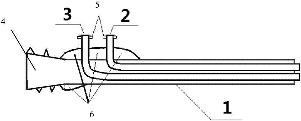
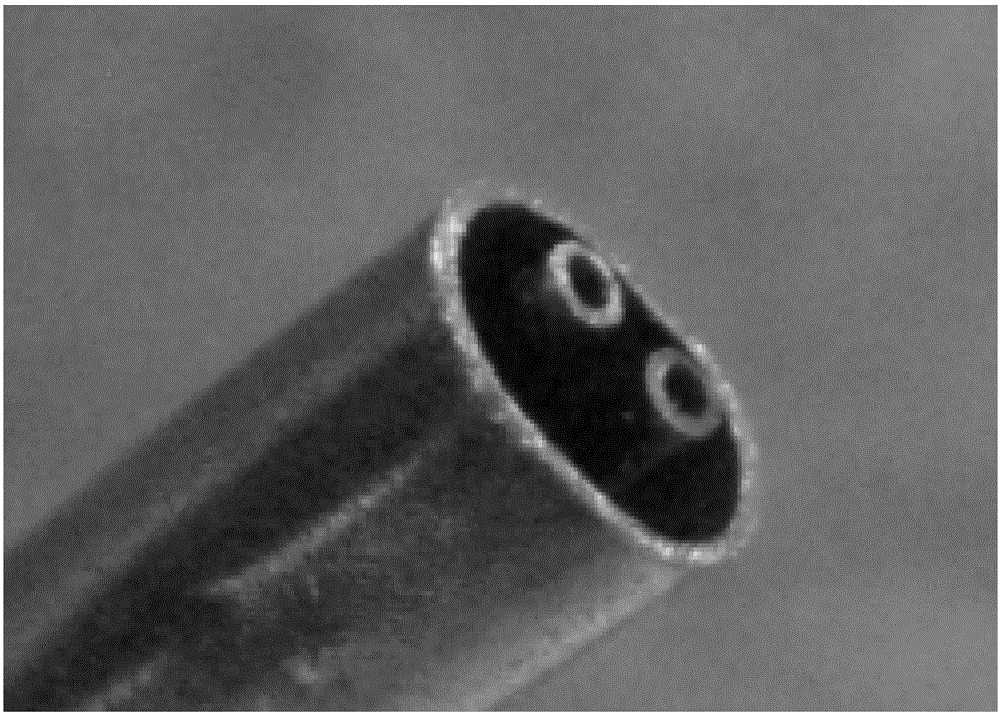
[0027] The present invention provides a coaxial microfluidic control nozzle containing split double cores, including a total capillary 1, a first curved capillary 2 and a second curved capillary 3; the first curved capillary 2 and the second curved capillary Two curved capillary tubes 3 are arranged side by side in the total capillary tube 1, and the curved ends of the first curved capillary tube 2 and the second curved capillary tube 3 pass through the side of the total capillary tube 1, so The other ends of the first curved capillary 2 and the second curved capillary 3 pass through the outlet end of the total capillary 1 and are flush with each other.

[0028] Further, the other ends of the first curved capillary 2 and the second curved capillary 3 pass through the outlet end of the total capillary 1 by 0.2 mm, and the first curved capillary 2 and the The distance between the second curved capillary 3 in the width direction is 0.2 mm, and the distance between the first curve...

Embodiment 2

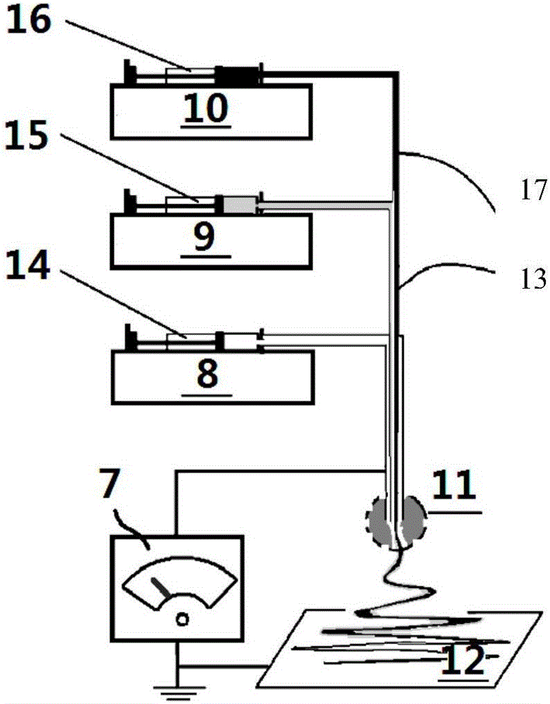
[0033] A high-voltage electrospinning device assembled using the nozzle of Example 1, its composition schematic diagram is as follows image 3 As shown, it includes a high-pressure generator 7, a first syringe pump 8, a second syringe pump 9, a third syringe pump 10, a coaxial microfluidic electrospray head 11 containing split double cores, a fiber receiving plate 12, a first high elastic Silicone hose 13, first syringe 14, second syringe 15, third syringe 16, second high elastic silicone hose 17.

[0034] A high-voltage electrospinning device with a coaxial microfluidic control nozzle containing split double cores is used to perform electrospinning on the three streams of fluids. The specific steps are: the first syringe 14 is installed in the first syringe pump 8, and the first syringe 14 A kind of sheath spinning liquid is added in, and the first syringe 14 is directly connected to the interface 4 of the coaxial microfluidic control nozzle 11 containing split double cores. ...


PUM

PropertyMeasurementUnit
lengthaaaaaaaaaa
diameteraaaaaaaaaa

Abstract

The invention provides a coaxially split dual-core containing microfluid control nozzle comprising a chief capillary tube, a first bending capillary tube and a second bending capillary tube; the first bending capillary tube and a second bending capillary tube are arranged inside the chief capillary tube side by side; the bending end of each of the first bending capillary tube and the second bending capillary tube goes through from the side surface of the chief capillary tube; the other end of each of the first bending capillary tube and the second bending capillary tube goes through from an outlet end of the chief capillary tube. The invention also discloses a high voltage electrostatic spinning device applying the nozzle; the spinning device comprises a first syringe pump, a first injection syringe, a second syringe pump, a second injection syringe, a third syringe pump, a third injection syringe, a silica gel flexible pipe, a fiber receiving plate and a high pressure generator. An enforcement method of preparing coaxially split dual-core containing structural nanometer fiber is also provided; under high voltage electrostatic field, high voltage electrostatic spinning technology is carried out to effectively prepare nano fiber having complex structural features containing the coaxially split dual-core.

Description

technical field [0001] The invention belongs to the field of nanomaterials, and relates to a spinning device and a spinning method, in particular to a microfluidic control nozzle with a coaxial split core and a coaxial micro fluid control nozzle with a coaxial split core. A multi-fluid electrospinning device with a fluid control nozzle, and a single-step electrospinning method for preparing coaxial structural nanofibers containing split double cores using the device. Background technique [0002] High-voltage electrospinning technology, referred to as electrospinning, is a top-down nano-manufacturing technology. The jet is formed by overcoming the liquid surface tension and viscoelastic force of the droplets at the tip of the nozzle by applying an electric field force. Under the joint action of force and surface tension, the atomized liquid jet is bent, stretched, and split by high frequency, and it is stretched tens of millions of times in tens of milliseconds, and the na...

Claims


Application Information

Patent Timeline
Patent Type & Authority Applications(China)
IPC IPC(8): D01D5/00
CPCD01D5/0069D01D5/0015
Inventor 余灯广刘新宽张瑶瑶张玲玲
Owner UNIV OF SHANGHAI FOR SCI & TECH
Why Eureka
Try Eureka