
Aquatic product drying machine and control method

A control method and technology for aquatic products, applied in the direction of progressive dryers, dryers, drying solid materials, etc., can solve the problems of low economic benefits, destruction of nutrients in aquatic products, low level of drying condition control, etc., and achieve drying effect The effect of uniformity, improving work efficiency and shortening production time

Inactive Publication Date: 2017-04-19
XIAMEN UNIV OF TECH
View PDF17 Cites 8 Cited by
  • Summary
  • Abstract
  • Description
  • Claims
  • Application Information

AI Technical Summary

Problems solved by technology

[0003] This method depends on the natural climate conditions, the control level of the drying conditions is low, and the expected effect of the product cannot be guaranteed. After drying, the product index changes greatly, especially when the intensity of sunlight and air humidity cannot be controlled, the drying effect is extremely extreme. Low, not only can not guarantee the completion of drying on time, but also will cause uneven drying effect or even deterioration of the product
In addition, the hygienic conditions of the products are also difficult to be guaranteed.
[0004] Through the investigation of the drying results of aquatic products that currently use natural drying and other popular drying methods except microwave drying, it is found that these drying methods still used by most people have the following characteristics: natural methods cannot guarantee uncontrollable conditions such as weather and climate ;A variety of drying methods will lead to the destruction of the internal nutrients of aquatic products; long drying time and low efficiency; the interior of aquatic products is uneven after drying, and the effect is not up to standard; large consumption, high cost, and low economic benefit; different drying treatment methods Corresponding to different materials

Method used


Image

  • Aquatic product drying machine and control method
  • Aquatic product drying machine and control method
  • Aquatic product drying machine and control method

Examples


Embodiment Construction

[0039] The present invention will be further described in detail below in conjunction with the accompanying drawings and specific embodiments.

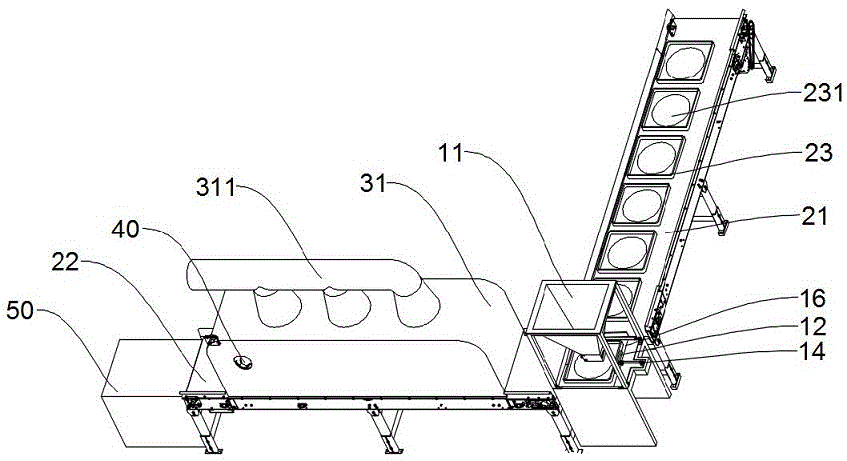
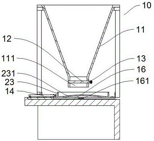
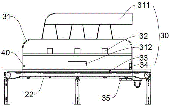
[0040] Examples, please refer to Figure 1 to Figure 4 , a kind of aquatic product drying machine, comprises feeding unit 10, transmission unit 20 and microwave drying unit 30, and described transmission unit 10 comprises first conveyer belt 21 and second conveyer belt 22, and described first conveyer belt 21 is placed with a plurality of Tray 23; the feed unit 10 includes a feed hopper 11, a push plate 12, a feed cylinder 13, a push plate cylinder 14, a first blocking cylinder 15 and a pallet backing plate 16, and the push plate 12 is located on the feed At the lower opening 111 of the material hopper 11, the feed cylinder 13 is connected to the push plate 12 to control the opening and closing of the lower opening 111, and the tray backing plate 16 is arranged below the push plate 12, so that The first blocking cylinder 15 is arrang...


PUM


Abstract

Disclosed is an aquatic product drying machine. The aquatic product drying machine comprises a feeding unit, a conveying unit and a microwave drying unit. The conveying unit comprises a first conveying belt and a second conveying belt, and a plurality of trays are placed on the first conveying belt. The feeding unit comprises a feeding funnel, a push plate, a feeding cylinder, a tray pushing cylinder, a first stopping cylinder and a tray base plate. The push plate is arranged at a lower opening of the feeding funnel. The feeding cylinder and the push plate are connected to be used for controlling the lower opening to be opened and closed. The tray base plate is arranged below the push plate. The first stopping cylinder is arranged between the tray base plate and the first conveying belt. The microwave drying unit is arranged on the second conveying belt and comprises a box body, a microwave generator, a capacitive sensor and a second stopping cylinder. The microwave generator is arranged inside the box body. The second stopping cylinder is arranged at an outlet of the box body. The capacitive sensor is arranged on a support corresponding to the second conveying belt and is used for detecting the reaching positions of the trays and sending signals to a control system, and thus the second stopping cylinder and the outlet of the box body are controlled to be opened and closed.

Description

technical field [0001] The invention relates to the technical field of drying equipment, in particular to an aquatic product dryer and a control method. Background technique [0002] Natural drying includes sunlight and air drying. Sunlight drying uses the heat energy generated by sunlight to evaporate the water contained in the product, and at the same time combines the wind factor to make the water vapor discharged from the aquatic product disappear into the air to achieve the effect of drying aquatic products; The wind force in the nature makes the air continuously blow over the surface of the aquatic products, taking away the water evaporated from the aquatic products to achieve the purpose of drying the aquatic products. This drying method is still the most widely used drying method so far due to almost no cost. [0003] This method depends on the natural climate conditions, the control level of the drying conditions is low, and the expected effect of the product cann...

Claims


Application Information

Patent Timeline
Patent Type & Authority Applications(China)
IPC IPC(8): F26B15/14F26B23/08F26B25/02F26B25/18
CPCF26B15/14F26B23/04F26B25/02F26B25/18
Inventor 林秉敬许娣
Owner XIAMEN UNIV OF TECH
Learn More