Composite wing integral oil tank and manufacturing method thereof

A technology of composite materials and integral fuel tanks, which is applied in the directions of wings, aircraft parts, transportation and packaging, etc., can solve the problems of reducing the utilization efficiency of wing fuel tanks, generating huge workload, fiber continuity damage, etc., and improving the structural utilization efficiency , Realize large-scale production, save assembly tooling and time

Active Publication Date: 2017-04-26
R&D INST OF CHINA AVIATION IND GENERAL AIRCRAFT
View PDF5 Cites 12 Cited by
  • Summary
  • Abstract
  • Description
  • Claims
  • Application Information

AI Technical Summary

Problems solved by technology

Especially for composite materials, a large number of fasteners and holes mean the consumption of a large number of special tools and man-hours, and bring about the destruction of fiber continuity and a higher possibility of damage, reducing the utilization efficiency of wing fuel tanks Increased cost and huge workload

Method used


Image

  • Composite wing integral oil tank and manufacturing method thereof
  • Composite wing integral oil tank and manufacturing method thereof
  • Composite wing integral oil tank and manufacturing method thereof

Examples


Embodiment Construction

[0021] The present invention will be described in further detail below in conjunction with the accompanying drawings.

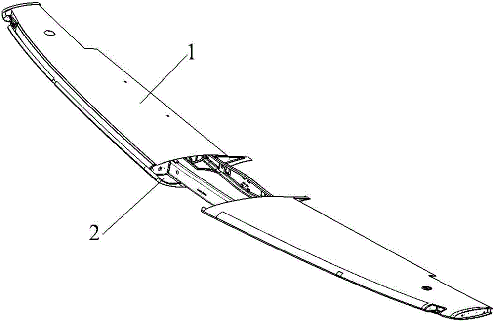
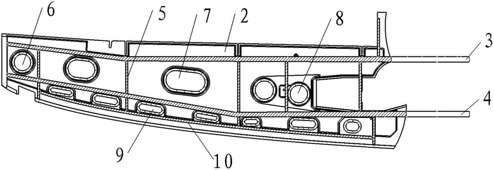
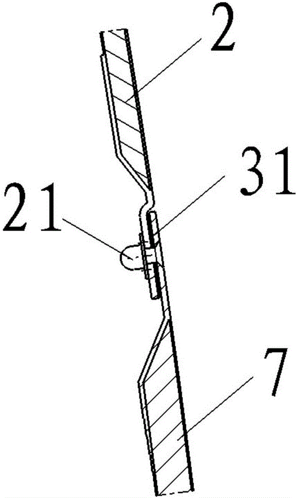
[0022] An integral oil tank of a composite wing, comprising an upper skin 1 and a lower skin 2; a beam is distributed between the upper skin 1 and the lower skin 2, which is divided into a front beam 3 and a rear beam 4, arranged in the direction of the wingspan, Between the front crossbeam 3 and the rear crossbeam 4, wing ribs 5 are distributed on the course, and between the wing fuel tank front wall 10 and the front crossbeam 3, there are leading edge fuel tank covers 9. Between the front crossbeam 3 and the rear crossbeam 4, a machine The wing fuel tank box section, the side of the box section close to the lower skin 2 is provided with a fuel tank cover 7 and a maintenance cover, the fuel tank cover 7 is connected to the lower skin 2 through a sealing nut, and a fuel sealing ring is arranged between the two 31, such as Figure 1~3 shown.

[0023] The abo...


PUM


Abstract

The invention relates to a composite wing integral oil tank. The composite wing integral oil tank comprises upper coverings 1, lower coverings 2, crossbeams and wing ribs 5, wherein each of the crossbeams is arranged between the corresponding upper covering 1 and the corresponding lower covering 2, the crossbeams are a front crossbeam 3 and a rear crossbeam 4, and each of the front crossbeams 3 and the corresponding rear crossbeam 4 are arranged in the spanwise direction; the wing ribs 5 are arranged between the corresponding front crossbeam 3 and the corresponding rear crossbeam 4 in the navigation direction; a front edge oil tank access cover 9 is arranged between each wing oil tank front wall 10 and the corresponding front crossbeam 3; a wing oil tank box section is formed between the corresponding front crossbeam and the corresponding rear crossbeam; each oil tank access cover 7 and a corresponding maintenance access cover are arranged on one side close to the corresponding lower covering 2, of the corresponding box section; and each of the oil tank access covers 7 is connected with the corresponding lower covering 2 through a corresponding sealing support plate nut 21, and a fuel oil sealing ring 31 is arranged between each of the oil tank access covers 7 and the corresponding lower covering 2. According to the composite wing integral oil tank disclosed by the invention, the manufacturing cost of composite airplanes is greatly reduced, the structural utilization efficiency is improved, the assembling tooling is saved, the assembling time is shortened, the workload is reduced, and the large-scale production of full-composite wing integral oil tanks is realized.

Description

technical field [0001] The invention relates to an integral fuel tank of an aircraft wing, in particular to an integral fuel tank of a composite material wing and a processing method thereof. Background technique [0002] Traditional aircraft wing fuel tanks are generally manufactured by aluminum alloy processing or expensive composite material autoclave forming process, so a large number of fasteners and holes are inevitably used in the wing fuel tank. Especially for composite materials, a large number of fasteners and holes mean the consumption of a large number of special tools and man-hours, and bring about the destruction of fiber continuity and a higher possibility of damage, reducing the utilization efficiency of wing fuel tanks Increased cost, and produce huge workload. Contents of the invention [0003] Aiming at the defects and deficiencies of traditional aircraft wing fuel tanks, what the present invention provides is a composite material wing integral fuel tan...

Claims


Application Information

Patent Timeline
Patent Type & Authority Applications(China)
IPC IPC(8): B64C3/34
CPCB64C3/34Y02T50/40
Inventor 蔡建丽张凌虎刘海涛曾小苗
Owner R&D INST OF CHINA AVIATION IND GENERAL AIRCRAFT
Why Eureka
Try Eureka