Pulp residue treating and recycling system

A technology of pulping and slag machine, which is applied in fiber raw material treatment, pulp beating/refining method, textiles and papermaking, etc. It can solve the problems of increasing the organic content of sewage, increasing the load of sewage treatment, affecting the effect of sewage treatment, etc., and achieving reduction Organic matter content, low production cost, and effects of reducing processing load

Active Publication Date: 2017-04-26
DONGGUAN NINE DRAGONS PAPER IND
View PDF7 Cites 6 Cited by
  • Summary
  • Abstract
  • Description
  • Claims
  • Application Information

AI Technical Summary

Problems solved by technology

Through inspection, it is found that the low-concentration and fine-screen tailings still contain some useful fibers. The existing technology discharges these tailings into the ditch, which on the one hand causes fiber loss and waste and increases production costs; , are all organic compounds, which will increase the content of organic matter in sewage, greatly increase the load of sewage treatment, affect the effect of sewage treatment, and are not environmentally friendly

Method used


Image

  • Pulp residue treating and recycling system

Examples


Embodiment 1

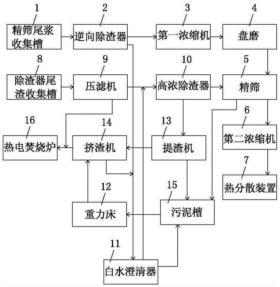
[0041] A kind of pulp slag processing recycling system of this embodiment, such as figure 1 As shown, it includes fine sieve tailings collection tank 1, reverse slag remover 2, first thickener 3, disc mill 4, fine sieve 5, second thickener 6, heat dispersion device 7, and slag remover tailings collection tank 8. Filter press 9, high-concentration slag remover 10, white water clarifier 11, gravity bed 12, slag extractor 13, slag extruder 14, sludge tank 15 and thermoelectric incinerator 16; among them, fine screen tailings are collected The fine screen tailings in the tank 1 are pumped to the reverse slag remover 2, the first output end of the reverse slag remover 2 is connected to the input end of the first concentrator 3, and the output end of the first concentrator 3 is connected to the disc mill 4 The input end is connected, the output end of the disc mill 4 is connected with the input end of the fine screen 5, the first output end of the fine screen 5 is connected with the...

Embodiment 2

[0049] Embodiment 2 of a pulp and residue treatment and recycling system of the present invention differs from Embodiment 1 in that, in this embodiment, the sieve width of the fine screen 5 is set to 0.2 mm. The fine sieve 5 with such a slit width can well separate non-fibrous components such as sand and fine ash in the tailings of the slag remover and the tailing slurry of the fine screen. Other structures and working principles of this embodiment are the same as those of Embodiment 1, and will not be repeated here.

Embodiment 3

[0051]Embodiment 3 of a pulp and residue treatment and recycling system of the present invention differs from Embodiment 1 in that, in this embodiment, the sieve width of the fine screen 5 is set to 0.3 mm. The fine sieve 5 with such a slit width can well separate non-fibrous components such as sand and fine ash in the tailings of the slag remover and the tailing slurry of the fine screen. Other structures and working principles of this embodiment are the same as those of Embodiment 1, and will not be repeated here.


PUM


Abstract

The invention relates to the technical field of papermaking and particularly relates to a pulp residue treating and recycling system. The system comprises a fine screen tail slurry collecting tank, a reverse residue separator, a first concentrator, a disc mill, a fine screen, a second concentrator, a thermal dispersion device, a residue separator tailing collecting tank, a press filter, a high-concentration residue separator, a white water clarifier, a gravity bed, a residue extracting machine, a residue squeezing machine, a sludge sump and a pyroelectric incinerator. According to the pulp residue treating and recycling system, un-dispersed fiber bundles in residue separator tailings and fine screen tail slurry can be scattered and dispersed again, and lightweight bubbles can be separated; and meanwhile, non-fibrous components such as sand and fine ashes can be further separated from the residue separator tailings and the fine screen tail slurry, so that the pulp residue treating and recycling system has the advantages that fiber loss can be reduced, the content of organic matters in discharged sewage is reduced, the sewage treatment load is reduced greatly, and finally, the energy-saving and environment-friendly social benefits are achieved.

Description

technical field [0001] The invention relates to the technical field of papermaking, in particular to a pulp residue treatment and recycling system. Background technique [0002] In the papermaking process, low-concentration cleaners and fine screens are required. In the prior art, the tailings discharged from the low-concentration slag remover and fine sieve are directly discharged to the ditch. Through inspection, it is found that the tailings of low concentration and fine screening still contain some useful fibers. The existing technology discharges these tailings into the ditch, which on the one hand causes fiber loss and waste and increases production costs; on the other hand, because the discharged tailings contain more fibers , are all organic compounds, which will increase the content of organic matter in sewage, greatly increase the load of sewage treatment, affect the effect of sewage treatment, and are not environmentally friendly. Contents of the invention [...

Claims


Application Information

Patent Timeline
Patent Type & Authority Applications(China)
IPC IPC(8): D21F1/66D21D1/30D21D5/02
CPCD21D1/303D21D5/02D21F1/66
Inventor 张成飞林新阳宋林林吴垠
Owner DONGGUAN NINE DRAGONS PAPER IND
Why Eureka
Try Eureka