Large-drift-diameter high-pressure rotation joint used for drilling machine
What is Al technical title?
Al technical title is built by PatSnap Al team. It summarizes the technical point description of the patent document.
A rotary joint, large-diameter technology, used in drill pipes, drill pipes, drilling equipment, etc., can solve the problems of slow grouting, increase work efficiency, increase flow rate, etc., and achieve fast hole forming speed, smooth slag discharge, and sealing. good performance
Inactive Publication Date: 2017-04-26
JIANGSU WUXI MINERAL EXPLORATION MASCH GENERAL FAB CO LTD
View PDF5 Cites 3 Cited by
Summary
Abstract
Description
Claims
Application Information
AI Technical Summary
This helps you quickly interpret patents by identifying the three key elements:
Problems solved by technology
Method used
Benefits of technology
Problems solved by technology
[0004] The purpose of the present invention is to solve the problem of slow drilling and grouting of existing rotary joints, and propose a large-diameter high-pressure rotary joint for drilling rigs. By improving the structure, increasing the diameter of the flow, and ingenious and reasonable layout of the sealing position, thereby increasing the Large flow rate, smooth and rapid slag discharge, increased hole forming speed, faster grouting speed and less clogging, increased work efficiency, saved time and cost, and greatly improved sealing performance
Method used
Image
Click on the blue label to locate the original text in one second.
Reading with bidirectional positioning of images and text.
Examples
Embodiment Construction
[0025] The present invention will be further described below in conjunction with specific drawings and embodiments.
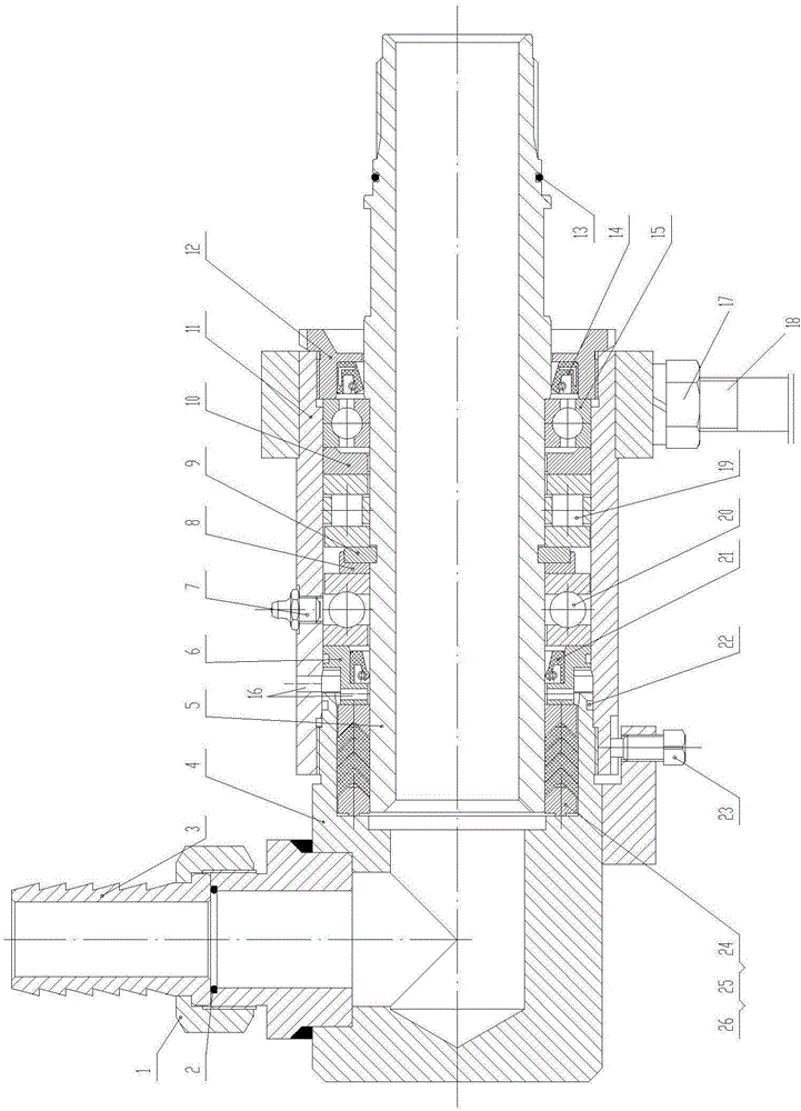
[0026] The drilling rig proposed by the present invention uses a large-diameter high-pressure rotary joint, such as figure 1 shown, including:
[0027] Socket nut 1, first O-ring 2, connecting pipe 3, gland joint 4, main shaft 5, first gasket 6, oil cup 7, retaining ring 8, key 9, second gasket 10, housing 11 , Lower cover 12, second O-ring 13, first oil seal 14, first bearing 15, nut 17, anti-rotation pin 18, second bearing 19, third bearing 20, second oil seal 21, third O-ring 22. Screw 23, pressure ring 24, V-shaped ring 25, support ring 26;
[0028] The gland joint 4 has two connected joint ends; the two joint ends of the gland joint 4 are approximately vertical;
[0029] The support ring 26, the V-shaped ring 25 and the compression ring 24 are sequentially pressed into the inner step of a joint end of the gland joint 4, the compression ring 24 is locate...
PUM
Abstract
The invention provides a large-drift-diameter high-pressure rotation joint used for a drilling machine. The large-drift-diameter high-pressure rotation joint used for the drilling machine comprises a mull-coupling nut, a first O-shaped ring, a connecting pipe, a gland joint, a main shaft, a first pad, a retainer ring, a clamping key, a second pad, a shell, a lower cover, a first oil seal, a first bearing, a second bearing, a third bearing, a second oil seal, a third O-shaped ring, a compression ring, a V-shaped ring and a supporting ring. The supporting ring, the V-shaped ring and the compression ring are sequentially compressed into an inner stage of one joint end of the gland joint. The second oil seal is compressed into the first pad. The first oil seal is compressed into the lower cover. The first bearing, the second pad, the second bearing, the clamping key, the retainer ring, the third bearing and the first pad are sequentially arranged on the main shaft in a sleeving mode. The clamping key is clamped into a key groove formed in the surface of the main shaft. The main shaft is riveted into the shell. The supporting ring, the V-shaped ring and the compression ring are arranged at one end of the main shaft in a sleeving mode. One end of the shell is connected with and fastened to one joint end of the gland joint. The throughput is increased since the sealing positions are ingeniously and reasonably arranged.
Description
technical field [0001] The invention relates to the technical field of construction tools in construction machinery foundation equipment, in particular to a high-pressure rotary joint for drilling rigs. Background technique [0002] In foundation construction, the soil layer is sometimes treated with anti-seepage, water-proof or reinforcement treatment, so fixed spraying, pendulum spraying or rotary spraying grouting will be carried out into the soil layer to achieve the purpose of anti-seepage and strengthening the bearing capacity of the foundation. However, during the drilling and grouting process of the conventional rotary joint, due to the small diameter, the slag discharge is not smooth, the hole formation is slow, the grouting efficiency is low, and it is easy to block, so the work efficiency is relatively low. [0003] On the other hand, the existing rotary joint structure still needs to be improved, and the main disadvantages include poor sealing performance and sho...
Claims
Application Information
Patent Timeline
Application Date:The date an application was filed.
Publication Date:The date a patent or application was officially published.
First Publication Date:The earliest publication date of a patent with the same application number.
Issue Date:Publication date of the patent grant document.
PCT Entry Date:The Entry date of PCT National Phase.
Estimated Expiry Date:The statutory expiry date of a patent right according to the Patent Law, and it is the longest term of protection that the patent right can achieve without the termination of the patent right due to other reasons(Term extension factor has been taken into account ).
Invalid Date:Actual expiry date is based on effective date or publication date of legal transaction data of invalid patent.
Patent Type & Authority Applications(China)
IPC IPC(8): E21B17/05
CPCE21B17/05
Inventor 朱利根
Owner JIANGSU WUXI MINERAL EXPLORATION MASCH GENERAL FAB CO LTD