Taking-out and placing-in device used for carbon fiber continuous oil-sucking rod

A sucker rod and carbon fiber technology, which is applied in the direction of drill pipe, drill pipe, casing, etc., can solve the problems of unstable clamping, scattered rods in the drum, and inaccurate clamping positions, etc. Fast, easy-to-use results

Inactive Publication Date: 2017-04-26
BC P INC CHINA NAT PETROLEUM CORP +2
View PDF7 Cites 4 Cited by
  • Summary
  • Abstract
  • Description
  • Claims
  • Application Information

AI Technical Summary

Problems solved by technology

[0004] But existing above-mentioned two kinds of structures have the following problems: (1) when carrying out carbon fiber rod lowering and hoisting operation with the mode that the drum directly provides power, because the load at the bottom of the well is too large, especially when lifting encounters jamming, the drum cannot provide enough In particular, the lifting force required by the carbon fiber continuous sucker rod site needs to reach 10 tons to 15 tons, but when the drum is used for direct lifting, due to the strength of the drum and the limitation of the connection, it cannot meet this requirement; ( 2) When the hoisting device is directly hoisted above the wellhead, because the hoisting device cannot be completely fixed, it is easy to shake due to the influence of tension and various external environments, resulting in the carbon fiber continuous sucker rod being unable to accurately center the wellhead, and the carbon fiber continuous sucker rod The sucker rod is also easy to shake in the wellbore, causing eccentric wear; (3) the existing lifting device has no limit on the upper and lower sides, so that the carbon fiber rod is easy to deviate from the clamping block of the lifting device, causing The clamping is unstable or the clamping position is not accurate; (4) Even if the existing drum and lifting device are used together, because the drum and the lifting device are in a non-linkage mode, the carbon fiber between the drum and the lifting device will continuously pump oil. The rod is easy to pull too much or too little, causing the drum row rod to be scattered or the carbon fiber continuous sucker rod to be broken

Method used


Image

  • Taking-out and placing-in device used for carbon fiber continuous oil-sucking rod
  • Taking-out and placing-in device used for carbon fiber continuous oil-sucking rod
  • Taking-out and placing-in device used for carbon fiber continuous oil-sucking rod

Examples


Embodiment Construction

[0030] The following will clearly and completely describe the technical solutions in the embodiments of the present invention with reference to the accompanying drawings in the embodiments of the present invention. Obviously, the described embodiments are only some, not all, embodiments of the present invention. Based on the embodiments of the present invention, all other embodiments obtained by persons of ordinary skill in the art without making creative efforts belong to the protection scope of the present invention.

[0031] Unless otherwise defined separately, directions such as up, down, front, back, left, and right mentioned herein are all in accordance with the present invention. figure 1 The directions of up, down, front, back, left, and right in the text shall prevail, and shall be explained together here.

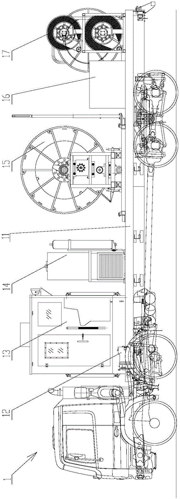
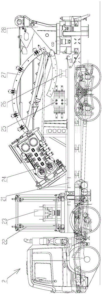
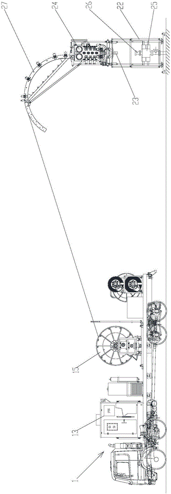
[0032] like Figure 1 to Figure 3 As shown, the present invention provides a lifting device for carbon fiber continuous sucker rods, which includes: a main vehic...


PUM

PropertyMeasurementUnit
Lengthaaaaaaaaaa

Abstract

The invention discloses a taking-out and placing-in device used for a carbon fiber continuous oil-sucking rod. The taking-out and placing-in device comprises a main vehicle and an auxiliary vehicle. A control chamber, a power output mechanism, a hydraulic mechanism and a roller are arranged on the main vehicle, an industrial personal computer (IPC) is arranged in the control chamber and connected with the power output mechanism, one end of the power output mechanism is connected with an engine of the main vehicle, the other end of the power output mechanism is connected with a first pump and a second pump of the hydraulic mechanism correspondingly, wherein the first pump is connected with the roller; and a well opening supporting frame, a scraper and an injecting head capable of being connected with the second pump are detachably arranged on the auxiliary vehicle, a truck with a crane is further arranged on the auxiliary vehicle, the well opening supporting frame can be fixed at a well opening, the injecting head can be fixed on the well opening supporting frame and opposite to the well opening, a guider is arranged on the injecting head, the scrapper can be fixed at the lower end of the injecting head, and the carbon fiber continuous oil-sucking rod which winds around the roller can penetrate through the injecting head and the scrapper along the guider, and is taken out from or placed in an oil well through the injecting head. According to the taking-out and placing-in device, placing in and taking out of the carbon fiber continuous oil-sucking rod can be achieved conveniently and rapidly.

Description

technical field [0001] The invention relates to the technical field of oil well exploitation, in particular to a tripping device for a carbon fiber continuous sucker rod, in particular to a special device for running a flat carbon fiber composite continuous sucker rod into and out of an oil well. Background technique [0002] Carbon fiber composite continuous sucker rod is a new type of flexible sucker rod, which has the properties of no coupling, light weight, high strength, high temperature resistance, corrosion resistance, etc. In the pumping well, carbon fiber continuous sucker rod is used instead of ordinary steel The oil rod can greatly reduce the energy consumption of oil production. Due to the relatively large bending radius of carbon fiber materials, flat carbon fiber continuous sucker rods with a size of about 32mm×3.4mm are generally used in the society to reduce the bending radius and make the radius of the drum winding carbon fiber rods smaller. [0003] The ex...

Claims


Application Information

Patent Timeline
IPC IPC(8): E21B19/22
CPCE21B19/22
Inventor 杨志敏刘寿军李雪辉杨高张富强段文益刘菲
Owner BC P INC CHINA NAT PETROLEUM CORP
Why Eureka
Try Eureka