Dynamic measuring device of micro force

A technology of dynamic measurement and micro force, which is applied in the direction of measuring devices, measuring fluid pressure, instruments, etc., can solve the problems of limited progress in the application limit of microelectronics, marginal effects, etc., to achieve measurement span, adjustable accuracy, avoid The effect of the experimental conditions required

Active Publication Date: 2017-04-26
BEIJING INST OF SPACECRAFT ENVIRONMENT ENG
View PDF7 Cites 5 Cited by
  • Summary
  • Abstract
  • Description
  • Claims
  • Application Information

AI Technical Summary

Problems solved by technology

With the continuous development of the microelectronics industry, relevant technical solutions will become more mature, but at the same time there will be marginal effects, and its progress will be increasingly limited by the application limit of microelectronics

Method used


Image

  • Dynamic measuring device of micro force
  • Dynamic measuring device of micro force
  • Dynamic measuring device of micro force

Examples


Embodiment Construction

[0028] The present invention will be described in detail below in conjunction with the accompanying drawings and specific embodiments.

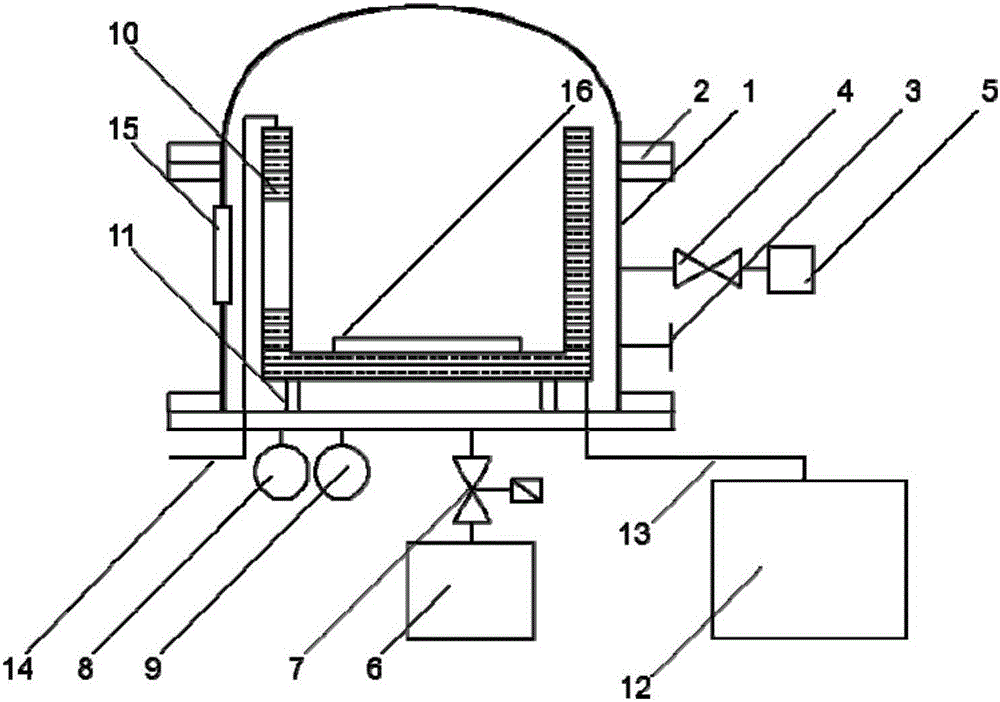
[0029] see figure 1 , figure 1It is a schematic diagram of the high-vacuum heat sink system in the micro-force dynamic measurement device of the present invention; the micro-force dynamic measurement device of the present invention includes three parts: a high-vacuum heat sink system, a magnetic levitation rotor system, and a speed measurement system. The high-vacuum heat sink system includes a The vacuum tank body 1 includes a heat sink 10 filled with liquid nitrogen inside the tank body. The inside of the cavity of the heat sink 10 is a magnetic levitation rotor system. Bolts are pressed and sealed, and the upper curved top cover is equipped with gas spring 2 to assist, which can be easily opened during assembly and debugging. There are three flange interfaces 3 on its side wall for connecting external circuits and interacting with other ...


PUM

PropertyMeasurementUnit
diameteraaaaaaaaaa

Abstract

The invention discloses a dynamic measuring device of a micro force. The dynamic measuring device is composed of three sub systems: a high vacuum heat sink system, a magnetic suspension rotor system, and a speed measurement system. The magnetic suspension rotor system consisting of a superconducting guide rail, a rotating shaft, brackets, and blades is arranged in the high vacuum heat sink system. Light reflectors are arranged at the blades in the speed measurement system; and the other parts of the speed measurement system are arranged outside the high vacuum heat sink system. In a low-temperature state, the superconducting guide rail in the magnetic suspension rotor system enables the other part, being the rotor part, of the magnetic suspension rotor system to be suspended stably, so that the contact friction can be eliminated and only one plane revolution freedom degree can be kept. The measured thrust is attached to one surface of each blade of the magnetic suspension rotor system, so that the rotor accelerates continuously; and in the low-temperature high-vacuum environment provided by the high vacuum heat sink system, the rotating speed time curve of the magnetic suspension rotor system is obtained by the speed measurement system through the observation window and calculation is carried out further to obtain the measured thrust.

Description

technical field [0001] The invention relates to an experimental device for accurately measuring tiny forces, in particular to a combination device of a vacuum suspension system and a small rotating system. Background technique [0002] Micro Force Measuring Pointer Pair 10 -5 The force below N can be accurately measured, and it has broad application prospects and unshakable practical status in the development of high-tech fields such as nanotechnology, micro-nano manufacturing, biomedicine, and aerospace micro-propulsion. At present, the known micro-force measurement systems have four main directions, including atomic force microscope cantilever beam technology, measurement based on micro-friction characteristics, torque-type micro-force measurement technology, and electrostatic force-type micro-force measurement. [0003] The document "D.B.Newell, J.R.Pratt, J.A.Kramar, D.T.Smith and E.R.Williams. The NIST Microforce Realization and Measurement Project [J]. IEEE Transactio...

Claims


Application Information

Patent Timeline
Patent Type & Authority Applications(China)
IPC IPC(8): G01L11/00
CPCG01L11/00
Inventor 欧阳晓平何世熠夏彦姜利祥王三胜韩然欧学东沈自才
Owner BEIJING INST OF SPACECRAFT ENVIRONMENT ENG
Why Eureka
Try Eureka