
Numerically controlled machine tool remote monitoring method and device

A technology of numerical control machine tools and monitoring devices, applied in the direction of program control, computer control, general control systems, etc., can solve problems such as communication port conflicts, system downtime, communication protocol incompatibility, etc., achieve fast response and reduce difficulty

Inactive Publication Date: 2017-04-26
北京兰光创新科技有限公司
View PDF4 Cites 25 Cited by
  • Summary
  • Abstract
  • Description
  • Claims
  • Application Information

AI Technical Summary

Problems solved by technology

[0009] (1) There must be a stable and reliable network between each device and the server. Once the network is interrupted, events such as data loss, data errors, and system downtime often occur due to abnormal communication processes.
[0010] (2) Various communication protocols are incompatible. Multiple acquisition programs need to be deployed on one server, which requires different software and hardware environments for the server. Conflicts between communication ports used for acquisition are common;
[0011] (3) In the industrial environment, ordinary servers cannot meet the requirements of electromagnetic interference, oil pollution, vibration, and noise in the workshop, and can only be deployed in the IT center of the enterprise; the communication between the equipment layer and the server often needs to penetrate multiple layers of firewalls, but many equipment The collection protocol cannot communicate across network segments and is not compatible with firewall settings
[0012] (4) There is currently a lack of CNC machine tool acquisition hardware suitable for industrial environments in the market: with the above-mentioned acquisition technology, it can also solve the problems of protocol compatibility and deployment

Method used


Image

  • Numerically controlled machine tool remote monitoring method and device
  • Numerically controlled machine tool remote monitoring method and device
  • Numerically controlled machine tool remote monitoring method and device

Examples


Embodiment Construction

[0053]Embodiments of the present invention are described in detail below, and examples of the embodiments are shown in the drawings, wherein the same or similar reference numerals denote the same or similar elements or elements having the same or similar functions throughout. The embodiments described below by referring to the figures are exemplary and are intended to explain the present invention and should not be construed as limiting the present invention.

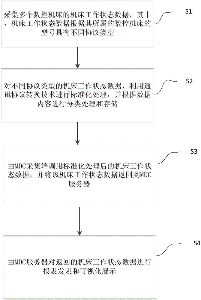
[0054] Such as figure 1 As shown, the CNC machine tool remote monitoring method in the embodiment of the present invention includes the following steps:

[0055] Step S1, collecting machine tool working status data of multiple CNC machine tools, wherein the machine tool working status data has different protocol types according to the models of the CNC machine tools to which they belong.

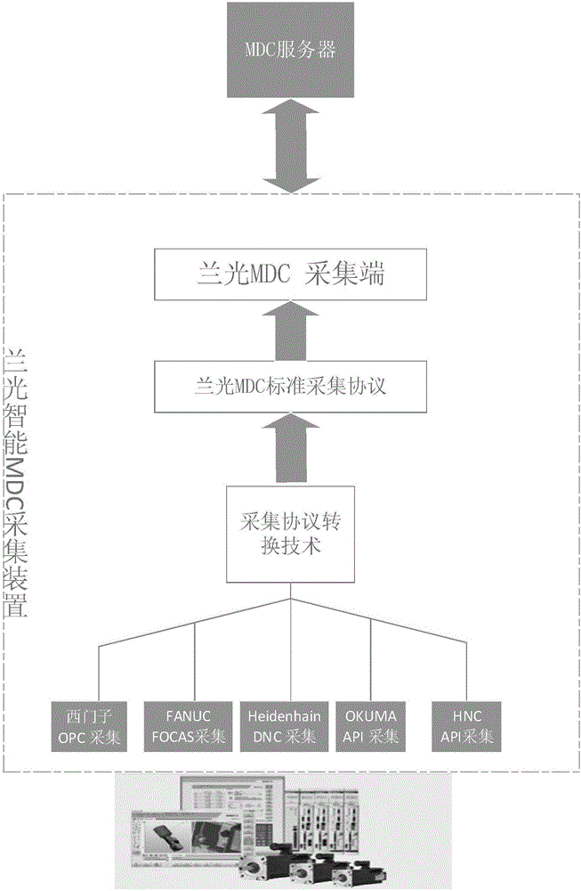
[0056] refer to figure 2 , The built-in communication protocol of the underlying acquisition device includes: Siemens OPC acquisi...


PUM


Abstract

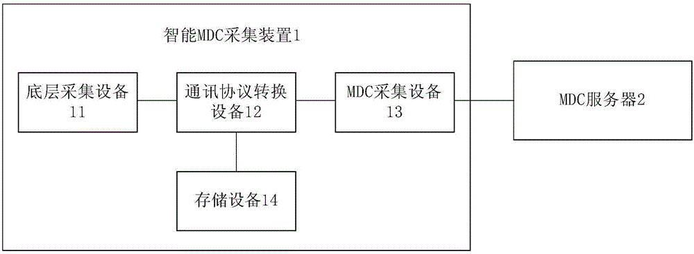
The invention brings forward a numerically controlled machine tool remote monitoring method and device. The remote monitoring method comprises the following steps: machine tool work state data of a plurality of numerically controlled machine tools is collected; machine tool work state data of different protocol types is subjected to standardization processing operation via communication protocol conversion technologies, the data is the subjected to type-based treating and storing operation according to data content, the machine tool work state data is called via an MDC collecting end after being subjected to the standardization processing operation, the machine tool work state data is returned to an MDC server, and the returned machine tool work state data is subjected to report form publication and visualized display operation via the MDC server. A plurality of CNC equipment communication protocols are embedded in the numerically controlled machine tool remote monitoring device, CNC type equipment data can be collected rapidly, and a direct point-to-point data collection mode can be changed to an indirect remote monitoring mode.

Description

technical field [0001] The invention relates to the technical field of CNC machine tool monitoring, in particular to a remote monitoring method and device for a CNC machine tool. Background technique [0002] On-line monitoring and data acquisition of CNC machine tools currently have the following methods: [0003] (1) Use the special communication protocol of the network card machine tool for data collection, such as the FOCAS protocol provided by Japan's FANUC company, the system manufacturer writes the machine tool operation process data into the intermediate protocol address, and the external computer reads the real-time operation information of the machine tool through the interface function , and analyze accordingly; [0004] (2) Use the standard OPC Server to communicate and collect data, communicate with the computer deployed by the OPC Server, and obtain the internal operation information of the machine tool through the OPC function library call; [0005] (3) Use ...

Claims


Application Information

Patent Timeline
Patent Type & Authority Applications(China)
IPC IPC(8): G05B19/4063
CPCG05B19/4063
Inventor 朱铎先
Owner 北京兰光创新科技有限公司
Learn More