Heat-dissipating-type capacitor placing device

A capacitor and heat-dissipating technology, which is applied in the field of heat-dissipating capacitor placement devices, can solve problems such as single function, complex operation, and incomplete heat dissipation, and achieve multiple economic benefits, reduce operating time, and complete heat dissipation.

Active Publication Date: 2017-04-26
QINZHOU POWER SUPPLY BUREAU OF GUANGXI POWER GRID CO LTD
View PDF4 Cites 10 Cited by
  • Summary
  • Abstract
  • Description
  • Claims
  • Application Information

AI Technical Summary

Problems solved by technology

[0007] In order to overcome the shortcomings of incomplete heat dissipation, single function and complicated operation of the existing capacitor placement device, the technical problem to be solved by the present invention is to provide a heat dissipation type capacitor placement device with complete heat dissipation, multiple functions and easy operation

Method used


Image

  • Heat-dissipating-type capacitor placing device
  • Heat-dissipating-type capacitor placing device
  • Heat-dissipating-type capacitor placing device

Examples


Embodiment 1

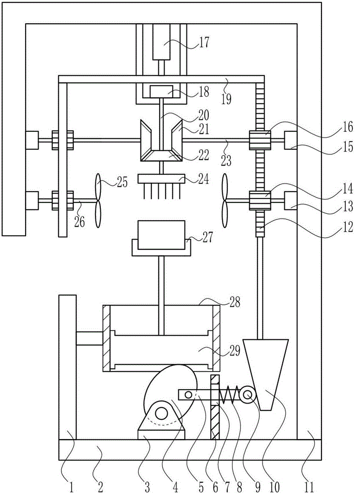
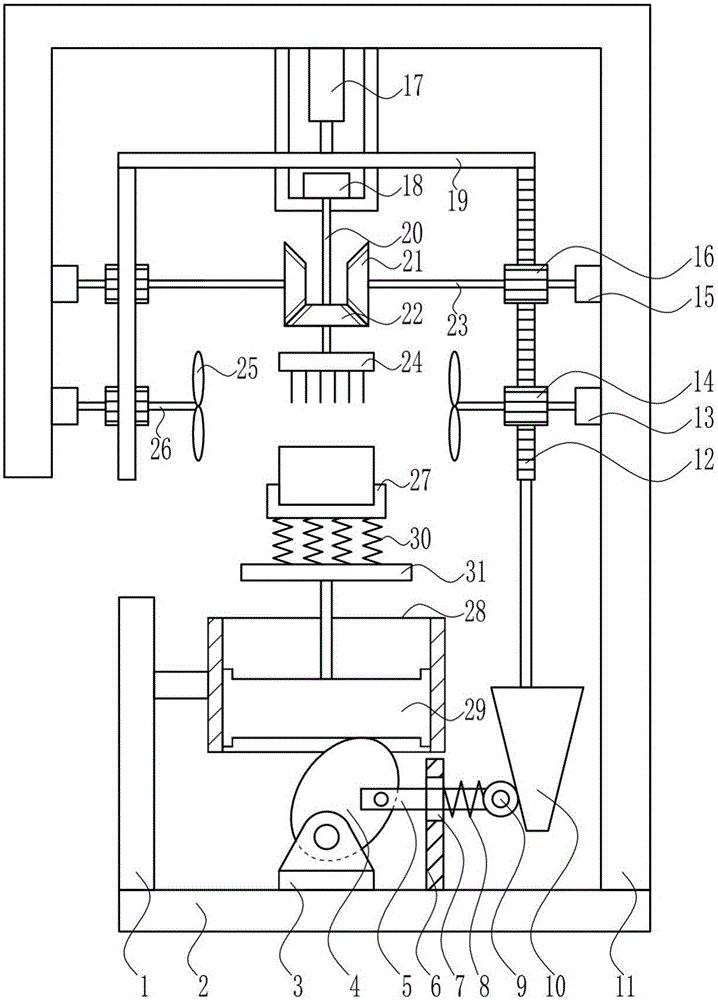
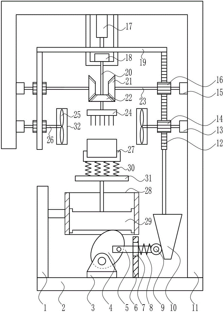
[0034] A heat sink type capacitor placement device such as Figure 1-4As shown, it includes support plate 1, bottom plate 2, swing seat 3, elliptical cam 4, moving rod 5, guide rod 6, first spring 8, contact roller 9, special-shaped block 10, right bracket 11, rack 12, the second One bearing seat 13, the first gear 14, the second bearing seat 15, the second gear 16, the electric push rod 17, the third bearing seat 18, the moving plate 19, the third rotating shaft 20, the second bevel gear 21, the first cone Gear 22, second rotating shaft 23, dust removal brush 24, blade 25, first rotating shaft 26, placement tank 27, cylinder body 28 and piston 29, the top of bottom plate 2 is provided with support plate 1 and swing seat 3 in sequence from left to right , guide rod 6 and right bracket 11, the right side of support plate 1 is provided with cylinder body 28, is provided with piston 29 in cylinder body 28, and piston 29 top is provided with placement groove body 27, is connected ...


PUM


Abstract

The invention relates to a capacitor placing device, especially relates to a heat-dissipating-type capacitor placing device, and is to solve the technical problem of providing the heat-dissipating-type capacitor placing device, which is full in heat dissipation, various in function and simple to operate. In order to solve the technical problem above, the invention provides the heat-dissipating-type capacitor placing device, which comprises a support plate, a bottom plate, a swing base, an ellipse cam, a moving rod, a guide rod, a first spring, a contact roller, a special-shaped block, a right support, a toothed bar and a first bearing pedestal and the like. The top portion of the bottom plate is provided with the support plate, the swing base, the guide rod and the right support in sequence from the left to right; the right side of the support plate is provided with a cylinder body; the cylinder body is internally provided with a piston; and the top portion of the piston is provided with a placing tank body. The heat-dissipating-type capacitor placing device achieves effects of full heat dissipation, various functions and simple operation; the device can start the functions of heat radiation and cooling and dust removing and the like simultaneously, thereby realizing function diversity of the device; and a capacitor can work better.

Description

technical field [0001] The invention relates to a capacitor placement device, in particular to a cooling type capacitor placement device. Background technique [0002] The heat dissipation methods include radiation heat dissipation, conduction heat dissipation, convection heat dissipation, and evaporation heat dissipation. [0003] Capacitors, usually referred to as capacitance for their ability to hold charges, are denoted by the letter C. Definition 1: A capacitor, as the name implies, is a 'charged container', a device that holds charges. Capacitors are one of the electronic components widely used in electronic equipment, and are widely used in DC blocking, coupling, bypass, filtering, tuning loops, energy conversion, control, etc. in circuits. Definition 2: Capacitor, any two conductors that are insulated from each other and are very close to each other form a capacitor. [0004] To place means to put on hold, to place. [0005] The existing capacitor placement devic...

Claims


Application Information

Patent Timeline
Patent Type & Authority Applications(China)
IPC IPC(8): H01G2/08H01G2/00
CPCH01G2/00H01G2/08
Inventor 阮茶英
Owner QINZHOU POWER SUPPLY BUREAU OF GUANGXI POWER GRID CO LTD
Why Eureka
Try Eureka