Method for measuring movement velocity of high-density plasma and optical system

A technology of plasma and motion speed, applied in the direction of plasma, optics, optical components, etc., can solve the problems of not being intuitive enough, adding electronic equipment and time synchronization links, etc., to achieve easy implementation, simple principle of optical path system, reasonable and accurate results Effect

Active Publication Date: 2017-04-26
NORTHWEST INST OF NUCLEAR TECH
View PDF5 Cites 8 Cited by
  • Summary
  • Abstract
  • Description
  • Claims
  • Application Information

AI Technical Summary

Problems solved by technology

[0004] Laser shadows are usually used to visually reflect the Z-pinch ablation flow and the implosion process. In order to obtain the motion velocity of the high-density plasma boundary, at least two frames of shadow diagnosis mus

Method used


Image

  • Method for measuring movement velocity of high-density plasma and optical system
  • Method for measuring movement velocity of high-density plasma and optical system
  • Method for measuring movement velocity of high-density plasma and optical system

Examples


Embodiment Construction

[0041] The present invention will be further described below in conjunction with the accompanying drawings and specific embodiments.

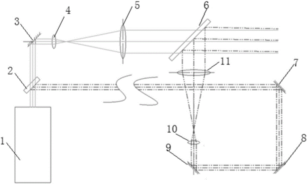
[0042] like figure 2 As shown, the beam generated by the sub-nanosecond pulse laser is divided into two beams through the optical path delay design, and a certain small angle is formed (mainly to facilitate the separation of subsequent beams): the laser beam is divided into two beams by the first beam splitter 2, The first light beam forms parallel light after the double lens (the fourth lens 4, the fifth lens 5) beam expansion, and the beam expansion ratio is determined by the focal length ratio of the two lenses, and the parallel light beam is used for imaging through the second beam splitter 6; After the light beam is delayed by the optical path of the second reflector 7, the third reflector 8, and the fourth reflector 9 (the delay time can be adjusted by the distance), the beam is expanded by the sixth lens 10 and the seventh lens 11 , th...


PUM


Abstract

The invention provides a method for measuring movement velocity of a high-density plasma and an optical system. On the basis of a principle of light refraction occurrence at a high-density-gradient plasma boundary, an optical system is designed to generate two light beams with incidence at small angles, wherein the directions of the two light beams are perpendicular to the movement direction of the plasma boundary; and a 4f system is used for imaging and separation of the two light beams: a first light beam and a delay beam is realized at a focal point of a first lens. When velocity measurement is carried out, some light of the first light beam is deflected at the boundary of the plasma in high-speed movement and the deflected light enters the optical system where the delay beam is located; an image of the boundary of the plasma at a corresponding time is displayed at a camera; after time delay of the delay beam, the shape and location of the plasma at the corresponding time are displayed at the camera; and average movement velocity information of the plasma boundary at a corresponding time interval can be obtained in a shadow image. With a laser shadow system, the velocity of the boundary of the plasma in high-speed movement can be obtained effectively; and the result is reasonable and accurate.

Description

technical field [0001] The invention relates to a method and system for measuring the motion velocity of high-density plasma based on the principle of laser shadow imaging. Background technique [0002] Laser shadow imaging is widely used in pulsed discharge plasma, high-energy laser-matter interaction, shock wave physics, and astrophysics. It is generally combined with laser schlieren and interference methods for optical diagnosis of the above processes to obtain clear physical The image and shadow imaging method can intuitively reflect the qualitative information such as the shape, position and instability development of the detection area. Its basic imaging principle is as figure 1 As shown, the object to be measured is placed on the focal point of lens a, and lens b is confocal with lens a, so that the shadow is imaged on the other focal point of lens b, and the ratio of image size is the ratio of focal lengths. [0003] In the study of high-power Z-pinch, gas or wire ...

Claims


Application Information

Patent Timeline
IPC IPC(8): H05H1/00G02B17/08
CPCG02B17/08H05H1/0025
Inventor 张金海李阳李沫盛亮孙铁平王亮平
Owner NORTHWEST INST OF NUCLEAR TECH
Why Eureka
Try Eureka