Double-high-voltage inorganic super capacitor

A supercapacitor, dual high-voltage technology, applied in the direction of hybrid box/shell/package, etc., can solve the problems of high internal resistance, poor environmental tolerance, poor pressure tolerance, etc.

Inactive Publication Date: 2017-05-03
HUBEI SHENGRONG TECH CO LTD
View PDF5 Cites 0 Cited by
  • Summary
  • Abstract
  • Description
  • Claims
  • Application Information

AI Technical Summary

Problems solved by technology

[0004] The technical problem to be solved by the present invention is to provide a safer and pressure-resistant high-voltage inorganic series supercapacitor, which mainly solves the problem of excessive internal resistance caused by...

Method used


Image

  • Double-high-voltage inorganic super capacitor
  • Double-high-voltage inorganic super capacitor
  • Double-high-voltage inorganic super capacitor

Examples


Embodiment 1

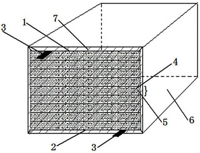
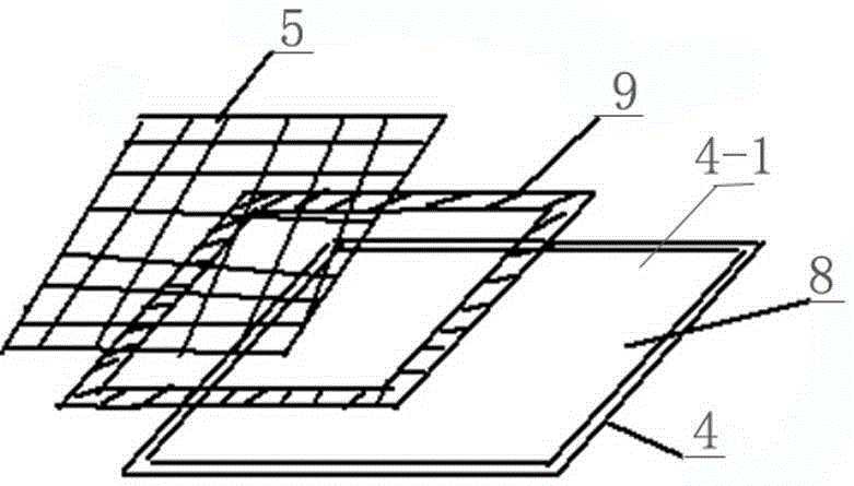
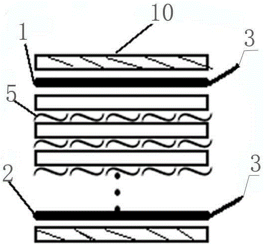
[0030] Embodiment 1: The dual high-voltage inorganic supercapacitor of this example has two electrode plates, which are respectively positive electrode plate 1 and negative electrode plate 2, and each of the two electrode plates extends a tab 3 for external power supply. There are at least 30 or more capacitor monomers between the two electrode plates, that is, the active material sheet 4. The active material sheet 4 is composed of the current collector sheet 4-1 and the activated carbon powder 8 coated on it. After the material sheet 4 is scraped, an insulating frame 9 is placed on it, and the adjacent capacitor cells are separated by a diaphragm 5, and then the capacitor cells stacked in series are put into a package casing 6 of the same size, and the stacking sequence is in accordance with the epoxy resin Strip 10, positive electrode plate 1, capacitor monomer, negative electrode plate 2, epoxy resin strip 10, use 5-13 T pressure to press the cover into the package shell 6 a...

Embodiment 2

[0031] Embodiment 2: In the dual high-voltage inorganic supercapacitor of this example, 4 active material sheets are 90 sheets, and 4 electrode sheets are taken. The stacking order is to take electrode sheet A, 30 active material sheets, and take electrode sheet B, 30 sheets. 1 sheet of active material, take electrode plate C, 30 active material sheets, take electrode plate D, and the rest of the operations are the same as in Example 1.

[0032] When the external power supply is connected, the tab of the electrode plate A and the tab of the electrode plate C are welded together to form a new positive electrode, and the tab of the electrode plate D and the tab of the electrode plate B are welded together to form a new positive electrode. of the negative electrode. After assembly, it is a 24 V, 18 mΩ, 45 F high-voltage supercapacitor, which is mainly used for starting heavy trucks. The maximum voltage for short-term overcharge is 28 V, and it can charge and discharge stably at a...


PUM


Abstract

The invention relates to a double-high-voltage inorganic super capacitor which comprises a packaging casing, an epoxy resin strip, a positive power-taking plate, single capacitor bodies, a negative power-taking plate and another epoxy resin strip are stacked and compressed sequentially in the packaging casing. At least 30 single capacitor bodies are arranged between the positive and negative energy-taking plates, and are assembled by serial connection, and every two single capacitor bodies are separated from each other via a diaphragm. The problems that in present capacitor production, single capacitor bodies are low in consistency and causes too high internal resistance, low pressure tolerance and low environment tolerance during use are solved; the diagrams between the adjacent single capacitor bodies and a current collector are avoided from short circuit due to contact, and the single capacitor bodies are compressed via an external pressure, welded, and then sealed by epoxy resin; the internal resistance of a capacitor product is kept consistent by adjusting the pressure in the manufacturing process; and no adhesive or dispersant needs to be added, and the product stability is improved.

Description

technical field [0001] The invention relates to a double high-voltage inorganic supercapacitor, in particular to an improvement on the structure of the high-voltage supercapacitor. Background technique [0002] Supercapacitors, also known as electric double-layer capacitors, supercapacitors, when the applied voltage is applied to the two plates, the ions in the electrolyte will be adsorbed to the plates to complete the polarization. The charging and discharging process of the supercapacitor is always a physical process. There is no chemical reaction, so supercapacitors can be charged and discharged hundreds of thousands of times. Supercapacitor is a new type of energy storage device between traditional capacitors and batteries. It has the advantages of high power density, large capacity, long service life, maintenance-free, economical and environmentally friendly. [0003] For traditional inorganic supercapacitors, the voltage of a single cell generally does not exceed 1V. ...

Claims


Application Information

Patent Timeline
IPC IPC(8): H01G11/78H01G11/80
CPCY02E60/13
Inventor 陈辉陈楠
Owner HUBEI SHENGRONG TECH CO LTD
Why Eureka
Try Eureka