
Electrode lead

An electrode wire and electrode technology, applied in the direction of electrodes, internal electrodes, head electrodes, etc., can solve the problems of stimulation energy loss, large energy consumption of pulse generators, reducing battery life of pulse generators, etc., and prolong battery life. life, increase the effective contact area, and improve the effect of energy utilization

Pending Publication Date: 2017-05-10
SCENERAY
View PDF2 Cites 0 Cited by
  • Summary
  • Abstract
  • Description
  • Claims
  • Application Information

AI Technical Summary

Problems solved by technology

However, in the actual operation process, there is a certain degree of uncertainty in making the target electrode or medical device reach and stick to the target position well.
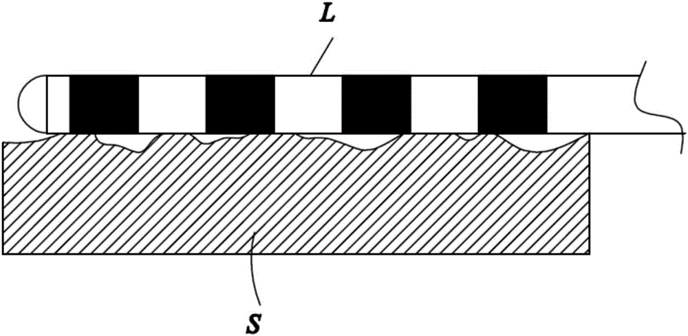
[0004] In the prior art, when the electrodes in the implantable brain electrical stimulation system are implanted in the position of the nuclei of the patient's brain, even if the doctor's surgical error is zero, due to the existence of nuclear magnetic resonance deviation, electrode drift, brain collapse, surgical head frame, etc. A variety of uncertain factors prevent the electrode from making good contact with the target stimulation site, and the traditional electrode is a straight electrode, and the outer surface of the electrode is roughly flush with the outer surface of the main tube, such as figure 1 As shown, due to the unevenness of the target stimulation position S in contact with the electrode lead L, there is a certain probability that the contact between the flat electrode and the target stimulation position S will not be sufficient if the traditional flat electrode is used for stimulation. In this case, the electrical signal will be transmitted to non-target stimulating functional groups such as interstitial fluid at the suspended position of the flat electrode, resulting in a certain loss of stimulation energy. At this time, the doctor may increase the stimulation energy in order to achieve the expected therapeutic effect. It will increase the side effects of stimulation, and increase the stimulation energy, which will make the energy consumption of the pulse generator connected to the electrode lead relatively large, thereby reducing the battery life of the pulse generator

Method used


Image

  • Electrode lead
  • Electrode lead
  • Electrode lead

Examples


Embodiment Construction

[0023] The present invention will be described in detail below in conjunction with specific embodiments shown in the accompanying drawings. However, these embodiments do not limit the present invention, and any structural, method, or functional changes made by those skilled in the art according to these embodiments are included in the protection scope of the present invention.

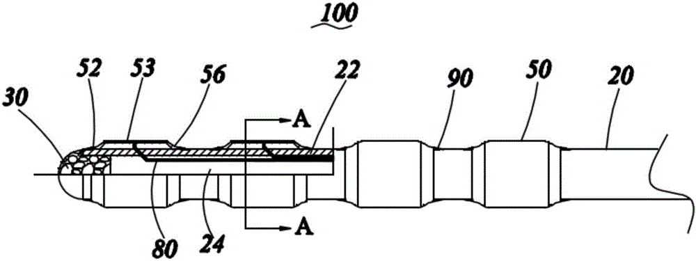
[0024] See figure 2 , The electrode lead 100 provided by the embodiment of the present invention includes a main body tube 20 , an end portion 30 disposed at one end of the main body tube 20 , an electrode 50 installed on the main body tube 20 , and a connecting wire 80 connected to the electrode 50 .

[0025] When the electrode lead 100 is used, the electrode lead 100 is placed in the diseased tissue, and the connecting lead 80 is connected to a pulse generator (not shown) and receives signals from the pulse generator to perform electrical stimulation therapy on the diseased tissue.

[0026] In this...


PUM


Abstract

The present invention provides an electrode lead. The lead comprises a main body tube and an electrode installed on the main body tube. The electrode comprises a matching portion matched with the main body tube, the electrode also comprises a projection portion connected with the matching portion, and the projection portion protrudes from the outer surface of the main body tube. The electrode of the electrode lead has a projection portion protruding from the main body tube and can improve the effective contact area of the electrode and a target stimulation position compared to a traditional flat and straight electrode to allow the electrode to fully contact the relatively rough organizational interface, increase the effectiveness of the stimulation, reduce the side effect caused by unnecessary big stimulation, improve the energy use efficiency of a pulse generator connected with the electrode wire and increase the service life of a battery of the pulse generator.

Description

technical field [0001] The invention relates to an electrode wire, especially an electrode wire used in the field of source intervention and implantation, such as a nerve stimulation electrode wire used for brain deep stimulation. Background technique [0002] Electrical nerve stimulation plays an important role in the treatment of nerve dysfunction and rehabilitation of nerve injury. The implantable nerve electrical stimulation system implants electrodes in specific nerves such as motor nerves and sensory nerves in the human body, and releases high-frequency electrical stimulation to stimulate specific nerves to restore human body functions to normal operation. body. At present, implantable electrical nerve stimulation systems mainly include implantable brain stimulation (DBS), implantable cortical stimulation (CNS), implantable spinal cord stimulation system (SCS), implantable vagus nerve electrical stimulation system (VNS), etc. [0003] Implantable brain stimulation (...

Claims


Application Information

Patent Timeline
Patent Type & Authority Applications(China)
IPC IPC(8): A61N1/05
CPCA61N1/0534
Inventor 潘祥生
Owner SCENERAY
Learn More