A Method for Determining the Machining Position of a Gear Shaft Keyway

A technology for processing position and determining method, applied in metal processing, metal processing equipment, metal processing mechanical parts, etc., can solve the problems of low accuracy of keyway processing position, affecting the service life of gear shaft, and keyway processing position error, etc. To achieve the effect of high measurement accuracy, convenient processing, and ensuring accuracy

Active Publication Date: 2018-10-12
SHANDONG JINCHEN MACHINERY CORP LTD LTD
View PDF7 Cites 0 Cited by
  • Summary
  • Abstract
  • Description
  • Claims
  • Application Information

AI Technical Summary

Problems solved by technology

[0002] The gear shaft has a wide range of applications in the mechanical field. In order to play the role of fixed transmission, the gear shaft needs to be machined with keyways. When in use, various types of keys are installed on the keyway to transmit power to the gear shaft. The accuracy of keyway processing directly affects Power transmission and the service life of the gear shaft, the inaccurate machining position of the keyway will lead to unstable operation of the gear shaft, severe wear, and reduce the life of the gear shaft. Therefore, there are strict requirements for the machining position of the keyway, such as figure 1 As shown in , it is required that the machined keyway symmetry line intersects with the center of the shaft section, and the keyway symmetry line is collinear with the shaft tooth or tooth groove symmetry line
[0003] At present, the methods for determining the machining position of the keyway on the gear shaft mainly include the tooth symmetry measurement method and the gear template processing method, such as figure 2 As shown, the main principle of the gear symmetry measurement method is to first set the gear shaft to be processed horizontally on the workbench of the boring machine or milling machine, pull the table on the straight shaft at both ends of the gear shaft to find the alignment, and then use the lever to measure the table 1 and the lever Measuring table 2 respectively measures the tooth heights of the two gear teeth that are symmetrical and approximately horizontal with respect to the gear shaft, rotate the gear shaft repeatedly until the heights of the two teeth are consistent, align the center of the gear shaft, and then machine the keyway on the gear shaft. This keyway processing method has the following disadvantages: first, it is only suitable for machining gear shafts with even numbers of teeth, but not suitable for machining gear shafts with odd numbers of teeth; Low
[0004] like image 3 As shown, the main principle of the gear template processing method is to make a template by wire cutting according to the standard value of the tooth shape of the gear shaft to be processed. When making a datum tooth template, the surroundings of the template are measurement datum planes A, B, C, D, where datum planes A and B are parallel to the datum alveolar centerline or the datum tooth centerline, and datum planes C and D are perpendicular Based on the reference tooth groove centerline or the reference tooth centerline, using the template processing method, the installation of the gear shaft is the same as the tooth symmetry measurement method, but before installation, the prepared template needs to be set on the gear shaft according to the gear tooth shape, and the keyway Before processing, use a dial indicator to find any measurement reference plane on the spur gear template. The above method has the following disadvantages: First, each gear shaft needs to customize templates of different specifications due to different gear modules and teeth numbers, which is poor in versatility. The processing cost is high; secondly, the sample plate is processed according to the standard size of the gear, and there is a machining error between the gear shaft to be processed and the standard gear, so there is an error between the size of the sample plate and the gear size on the gear shaft to be processed , resulting in a matching gap between the tooth shape of the template and the tooth shape on the gear shaft, and eventually leads to an error in the machining position of the keyway

Method used


Image

  • A Method for Determining the Machining Position of a Gear Shaft Keyway
  • A Method for Determining the Machining Position of a Gear Shaft Keyway
  • A Method for Determining the Machining Position of a Gear Shaft Keyway

Examples


Embodiment Construction

[0033] Below in conjunction with accompanying drawing and embodiment the present invention will be further described:

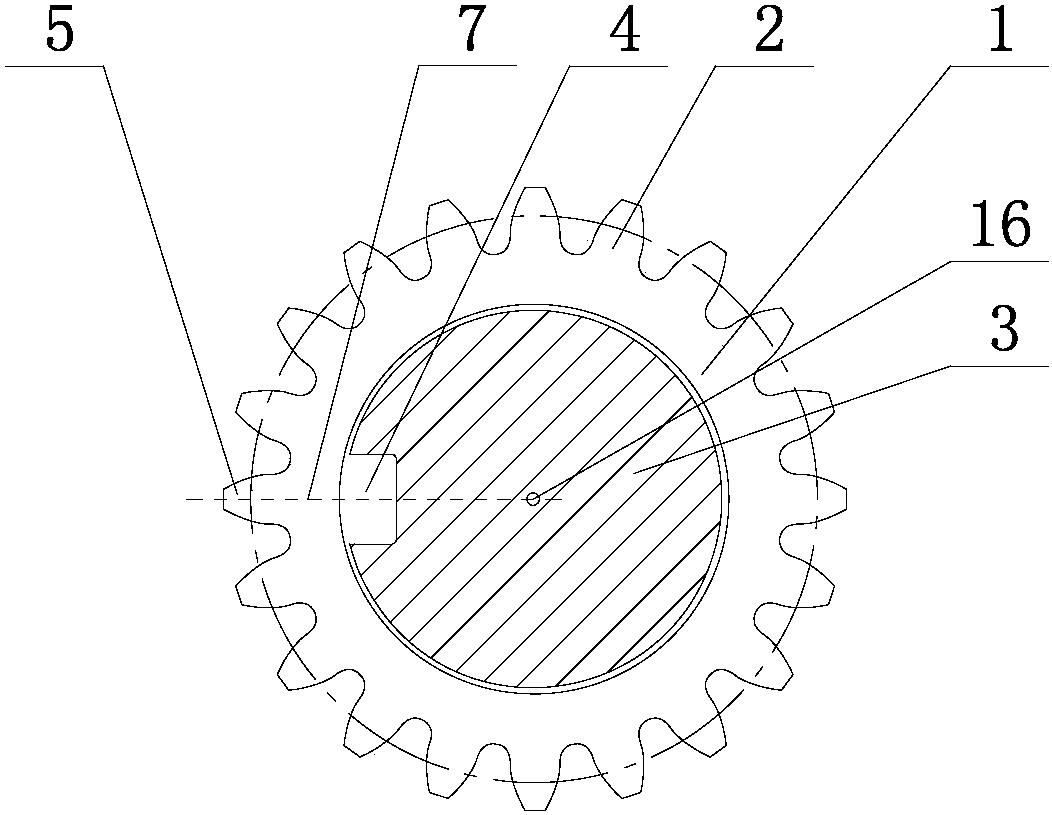
[0034] like Figure 1-5 As shown, a method for determining the machining position of a gear shaft keyway includes the following steps:

[0035] (1) Manufacture alignment process shaft

[0036] Set the modulus of gear shaft 1 and gear 2 to be processed as m (unit: mm), the tooth width as L1 (unit: mm), and the diameter of the addendum circle as d1 (unit: mm); the diameter of the alignment process shaft is D (unit: mm), the length is L (unit: mm);

[0037] Calibration process shaft diameter range: 1.8*m≤D≤2.5*m (unit: mm);

[0038] Alignment process axis length range: L≥L1+d1 / 2 (unit: mm);

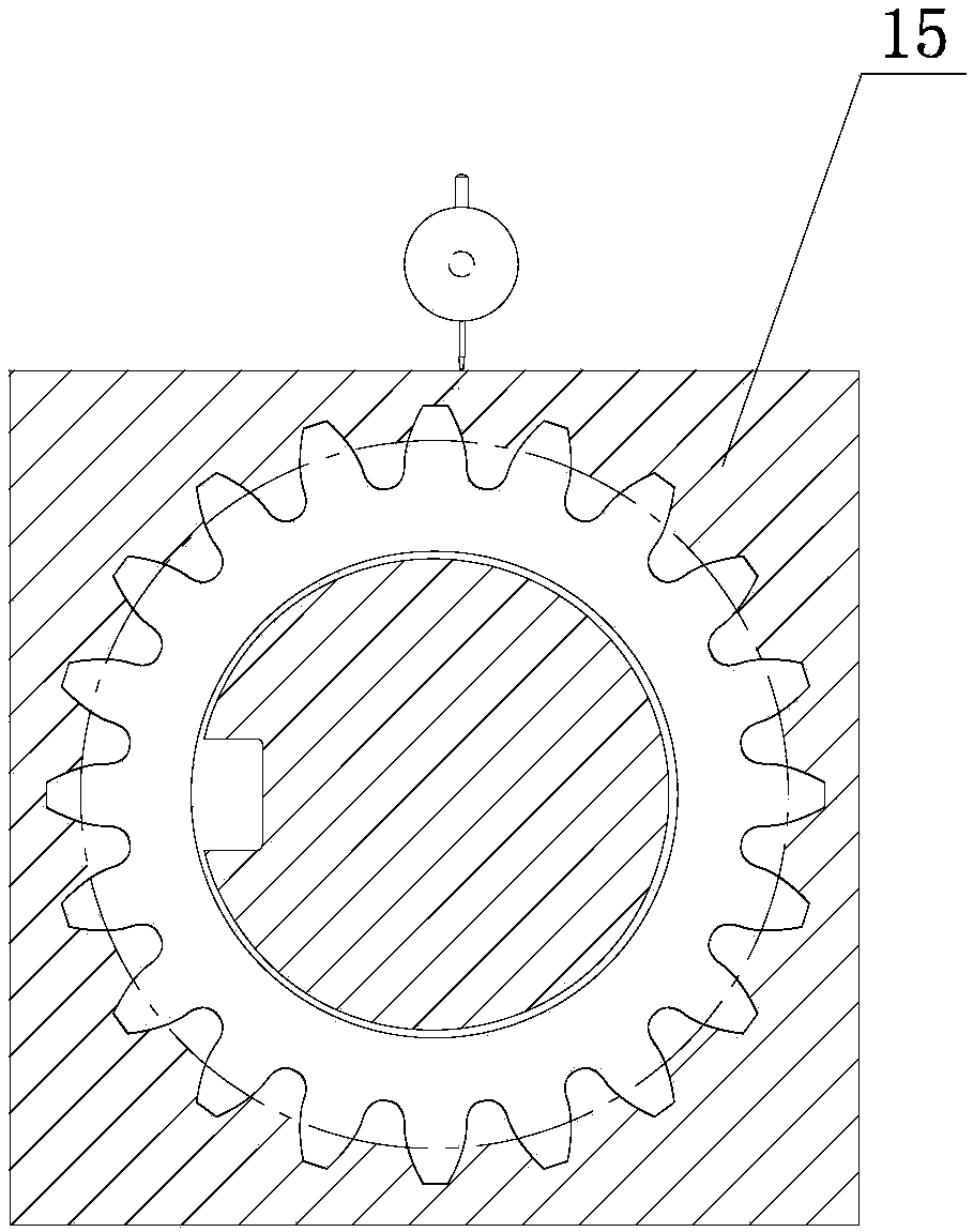
[0039] By replacing the traditional gear model 15 with the design of the process shaft, the structure is simpler and the processing cost is lower;

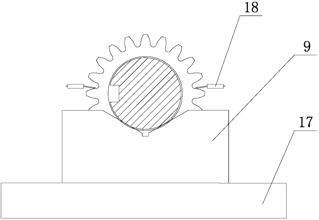
[0040] (2) Install the gear shaft 1 to be processed

[0041] Place the gear shaft 1 to be processed horizontally on the...


PUM


Abstract

The invention relates to a gear shaft key slot processing position determining method. A correcting process shaft is designed for replacing a conventional template; the structure is simpler; the tooth number of the gear shaft can be the even number or odd number; the processing is more convenient; the cost is lower; through the design of two V-shaped horizontal frames, the gear shaft is enabled to be horizontally arranged on a work table; the installation is more convenient and fast; a first correcting process shaft and a second correcting process shaft are enabled to be in a vertical plane by measuring the excircle highest point of the first correcting process shaft and the second correcting process shaft; the operability is high; the measuring precision is higher; a dial indicator is arranged on a machine tool main shaft; the dial indicator is used for determining the position of a boring head or a milling head. i.e., the processing center position of the key slot; the position precision is ensured. The gear shaft key slot processing position determining method provided by the invention has the advantages that the measuring tool is simple; the position detection is more accurate; the practicability is higher; the cost is low, and the like.

Description

Technical field: [0001] The invention relates to the technical field of keyway processing, in particular to a method for determining the machining position of a gear shaft keyway. Background technique: [0002] The gear shaft has a wide range of applications in the mechanical field. In order to play the role of fixed transmission, the gear shaft needs to be machined with keyways. When in use, various types of keys are installed on the keyway to transmit power to the gear shaft. The accuracy of keyway processing directly affects Power transmission and the service life of the gear shaft, the inaccurate machining position of the keyway will lead to unstable operation of the gear shaft, severe wear, and reduce the life of the gear shaft. Therefore, there are strict requirements for the machining position of the keyway, such as figure 1 As shown, it is required that the machined keyway symmetry line intersects with the center of the shaft section, and the keyway symmetry line is ...

Claims


Application Information

Patent Timeline
Patent Type & Authority Patents(China)
IPC IPC(8): B23C3/30B23Q15/22
CPCB23C3/30B23Q15/22
Inventor 姚镇波洪卫华
Owner SHANDONG JINCHEN MACHINERY CORP LTD LTD
Why Eureka
Try Eureka