Loop heat pipe evaporator assembling tool and assembling method

A technology for assembling tooling and loop heat pipes, used in manufacturing tools, metal processing, metal processing equipment, etc., can solve the problems of easy breakage, difficult deformation control, stuck capillary core, etc., to ensure product life and reliability. , to meet the small batch production, to avoid the effect of bending moment

Active Publication Date: 2017-05-10
BEIJING RES INST OF SPATIAL MECHANICAL & ELECTRICAL TECH
View PDF4 Cites 6 Cited by
  • Summary
  • Abstract
  • Description
  • Claims
  • Application Information

AI Technical Summary

Problems solved by technology

[0006] The traditional evaporator hot-packing process used in the assembly of the above-mentioned evaporator has the following disadvantages: First, it is difficult to control the deformation of the main shell A and the main shell B after welding, resulting in the coaxiality of the main shell A and the main shell B (that is, the cylindricity of the metal shell). ) is poor, and the assembly stroke between the capillary core and the metal shell is long during the hot-packing process, and it is easy to get stuck with the capillary core. It is necessary to ensure the high coaxiality of the main shell A and the main shell B after welding; secondly, in order to ensure that the loop heat pipe The requirement of long life requires that the surface of the evaporator should not be oxidized during the hot charging process, and it needs to be assembled in a vacuum furnace, which cannot be directly operated manually, so it needs to realize automatic assembly; moreover, because the capillary core is a slender rod structure, and it is made of powder sintered As a result, the bending strength is low, and the capillary core is easily broken if it is subjected to a bending moment when it is inserted into the metal shell; finally, there are grooves on the inner surface of the main shell A, and the friction between the capillary core and the main shell A is easy to scratch the surface of the capillary core during shrink fitting. Cause the powder on the surface of the capillary core to fall off, forming redundant residues, affecting the life of the product

Method used


Image

  • Loop heat pipe evaporator assembling tool and assembling method
  • Loop heat pipe evaporator assembling tool and assembling method
  • Loop heat pipe evaporator assembling tool and assembling method

Examples


Embodiment

[0067] An assembly tool for a loop heat pipe evaporator, the assembly tool includes a first set of tools, a second set of tools and a third set of tools;

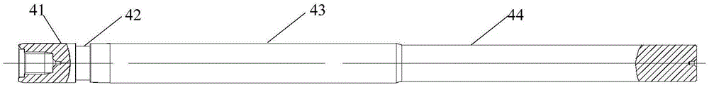
[0068] Such as Figure 5 As shown, the first set of tooling includes a mandrel 4, a counterweight 5, a limit block 6, a connecting rod 7, an upper plate 8, a support column 9, and a bottom plate 10;

[0069] Such as Figure 7 As shown, the second set of tooling includes a mandrel 4, a counterweight 5, a limit block 6, a main shell B support seat 11, a connecting rod 2 12, an upper plate 8, a support column 9, and a bottom plate 10;

[0070] Such as Figure 8 , Figure 9 and Figure 10 As shown, the third set of tooling includes a counterweight 5, an upper plate 8, a support column 9, a bottom plate 10, a limit support rod 13, an external threaded sleeve 14, an internal threaded sleeve 15, a protective terminal 16, and a main shell pull Cover 17, steel ball 18, steel ball seat 19, capillary core seat 20, collet 21.

[...


PUM

PropertyMeasurementUnit
lengthaaaaaaaaaa

Abstract

The invention relates to a loop heat pipe evaporator assembling tool and an assembling method mainly used for assembling an evaporator in a loop heat pipe and belongs to the technical field of two phase heat transmission of a loop heat pipe. According to the invention, on one hand, interference fit between a capillary core and a metal outer shell is realized, the situation that the capillary core does not crack after being mounted in the metal outer shell is ensured, the hot charging success rate is high, small-scale production can be met, the production cost is reduced, and the production efficiency is improved; and on the other hand, the surface of the capillary core is not scratched, powder does not fall off the surface of the capillary core, the product surface is free of oxidation and pollution, and the service life and the reliability of the product are prolonged and improved.

Description

technical field [0001] The invention relates to an assembly tool and assembly method for a loop heat pipe evaporator, which is mainly used for the assembly of the evaporator in the loop heat pipe, and belongs to the technical field of two-phase heat transfer of the loop heat pipe. Background technique [0002] Loop heat pipe two-phase heat transfer technology is currently one of the most cutting-edge thermal control technologies in the field of spacecraft thermal control. Long life and many other advantages. The evaporator is the core component of the loop heat pipe. The normal operation of the loop heat pipe requires the evaporator to have the dual functions of absorbing heat load and providing working fluid circulation power. The evaporator has an important impact on the operating performance and reliability of the loop heat pipe. [0003] The loop heat pipe evaporator is made of a capillary core and a metal shell through the interference assembly of the heat-fitting proc...

Claims


Application Information

Patent Timeline
Patent Type & Authority Applications(China)
IPC IPC(8): B23P11/02B23K15/04
CPCB23K15/04B23P11/025
Inventor 潘浩韩保辉江希龙吴杰张迪张志刚李星李松吕宠张硕罗世魁杨涛
Owner BEIJING RES INST OF SPATIAL MECHANICAL & ELECTRICAL TECH
Why Eureka
Try Eureka