

Z-direction micro displacement structure based on wedge feeding horizontal compensation
A micro-displacement and horizontal technology, which is applied in the direction of metal processing machinery parts, metal processing equipment, feeding devices, etc., can solve the problems of small working stroke, low precision, low positioning precision, etc., and achieve the effect of short stroke and low precision
- Summary
- Abstract
- Description
- Claims
- Application Information
AI Technical Summary
Problems solved by technology
Method used
Image

Examples
Embodiment Construction
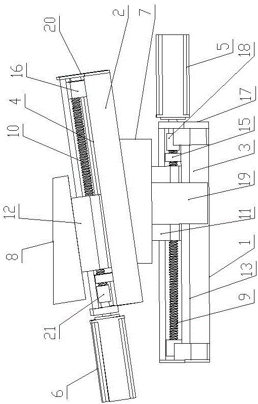
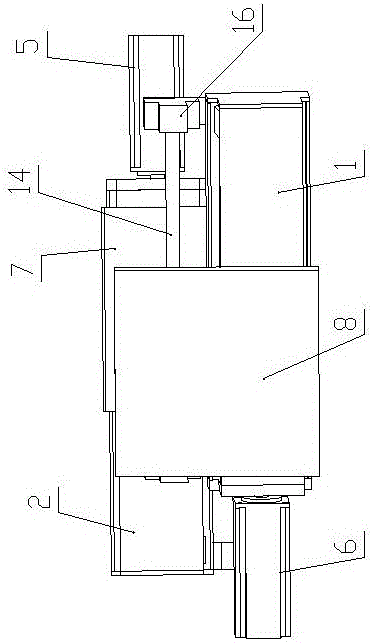
[0015] Such as figure 1 and figure 2 As shown, a Z-direction micro-displacement structure based on wedge feed horizontal compensation of the present invention includes a first installation frame 1, a second installation frame 2, a first linear slide rail 3, a second linear slide rail 4, a first A servo motor 5, a second servo motor 6, a first wedge block 7, a second wedge block 8, a first ball screw 9, a second ball screw 10, a first sliding pedestal 11, a second sliding pedestal 12, the first A polished rod guide rail 13, a second polished rod guide rail 14, a first support base 15 and a second support base 16;
[0016] The first linear slide rail 3 is horizontally arranged on the first installation frame 1 along the left-right direction, and the first installation frame 1 is provided with a first bracket 17 on the left upper part and the right upper part respectively, the first polished rod guide rail 13, the first ball bearing The lead screw 9 and the first linear slide ...
PUM
 Abstract
Description
Claims
Application Information