Pithead steam injection anti-leakage sealing device

A sealing device and anti-stab technology, which is applied in sealing/packing, wellbore/well parts, earthwork drilling and mining, etc. It can solve problems such as high hardness of surface spray welding layer or coating, failure of packing dry grinding, and potential safety hazards , to achieve the effect of improving dynamic sealing performance, ensuring effective sealing and avoiding puncture leakage

Active Publication Date: 2017-05-10
KARAMAY SHENGLI PLATEAU MACHINERY CO LTD
View PDF15 Cites 4 Cited by
  • Summary
  • Abstract
  • Description
  • Claims
  • Application Information

AI Technical Summary

Problems solved by technology

[0005] The packing sealing cavity and the polished rod are combined to form an annular counterbore, the space is narrow and deep, the rubber seals are difficult to take out or put in, the replacement work is troublesome, and the strength is high;
[0006] 2. There is no pressure observation valve or lubricating oil nozzle designed on the sealing box, so the downhole pressure cannot be predicted; when the downhole fluid supply is insufficient, lubricating oil cannot be added to the packing cavity, which will easily cause the packing to fail due to dry grinding and the sealing cycle will be short;
[0007] 3. The problem of eccentric wear cannot be effectively solved, and the sealing cycle is short;
[0008] 4. Under the high temperature and high pressure of steam injection, accidents such as puncture leakage, wellhead steam injection blowout and other accidents are prone to occur due to the problem of sealing packing materials
[0014] 1. The outer diameter tolerance range is large, generally -0.25mm to +0.13mm; the sealing effect with the inner hole of the packing is poor;
[0015] 2. There is no limit mark on the surface of the polished rod. During the lifting process, it is difficult to judge the position of the lower end, which may easily cause workover accidents;
[0016] 3. The hardness of the sprayed welding layer or coating on the surface is high, and the clips of the polished rod are easy to slip off, forming a safety hazard

Method used


Image

  • Pithead steam injection anti-leakage sealing device

Examples


Embodiment Construction

[0031] The present invention is not limited by the following examples, and specific implementation methods can be determined according to the technical solutions of the present invention and actual conditions.

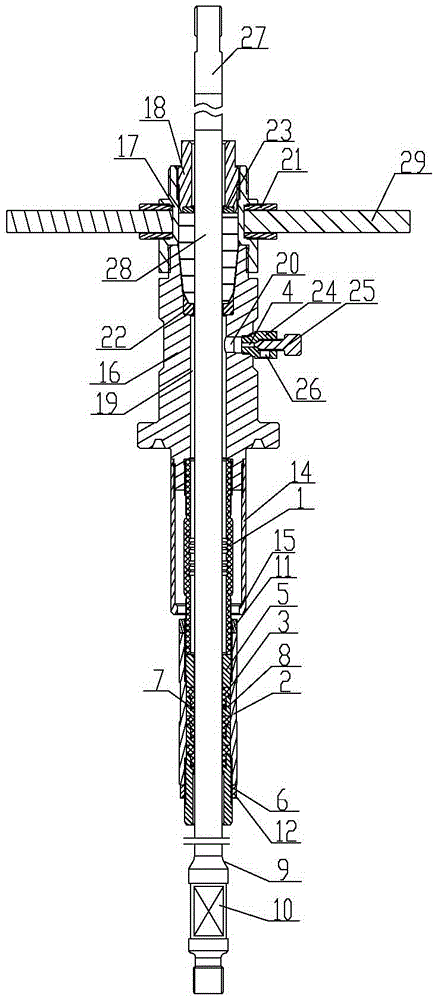
[0032] In the present invention, for the convenience of description, the description of the relative positional relationship of each component is based on the figure 1 The layout method is described, such as: the positional relationship of top, bottom, left, right, etc. is based on the attached figure 1 determined by the layout direction.

[0033] Below in conjunction with embodiment and accompanying drawing, the present invention will be further described:

[0034] as attached figure 1 As shown, the wellhead steam injection anti-puncture leakage sealing device includes a packing sealing assembly, a flexible pipe 1 and a secondary sealing assembly; the lower end of the packing sealing assembly is connected to a secondary sealing assembly through the flexible pipe 1; ...


PUM


Abstract

The invention relates to the technical field of pithead anti-jet device, and provides a pithead steam injection anti-leakage sealing device. The device comprises a packing seal assembly, a flexible pipe and a secondary sealing assembly. The lower end of the packing sealing assembly is connected with the secondary sealing assembly through the flexible pipe. The secondary sealing assembly comprises an anti-jet cylinder and a sealing part. The lower end of the flexible pipe is fixedly installed on the upper end of the anti-jet cylinder. At least one sealing part is arranged in the anti-jet cylinder. The sealing part is a high temperature and high pressure resistant sealing part. The pithead steam injection anti-leakage sealing device is reasonable and compact in structure, and convenient to use. The anti-jet cylinder uses the flexible pipe connected with the packing sealing assembly. The camber wear situation between a pole and the sealing part is avoided. At the same time, the applied high temperature and high pressure resistant sealing ring can be used for long term in the high temperature and high pressure environment during the steam injection. The leakage is avoided. The effective sealing is guaranteed. The packing becomes simpler. The automatic lubrication is available. The downhole pressure can be predicted. The pithead steam injection anti-leakage sealing device can improve the effect of the dynamic sealing performance at the pithead packing sealing assembly.

Description

technical field [0001] The invention relates to the technical field of wellhead blowout prevention devices, and relates to a wellhead steam injection anti-puncture leakage sealing device. Background technique [0002] Generally, the polished rod sealing device of rod production well is basically composed of polished rod sealing box, polished rod and rubber gate valve, which have the following disadvantages respectively: [0003] 1. Polished rod sealing box [0004] 1. The replacement of the packing is troublesome and labor-intensive; [0005] The packing sealing cavity and the polished rod are combined to form an annular counterbore, the space is narrow and deep, the rubber seals are difficult to take out or put in, the replacement work is troublesome, and the strength is high; [0006] 2. There is no pressure observation valve or lubricating oil nozzle designed on the sealing box, so the downhole pressure cannot be predicted; when the downhole fluid supply is insufficient...

Claims


Application Information

Patent Timeline
Patent Type & Authority Applications(China)
IPC IPC(8): E21B33/06
CPCE21B33/06Y02E10/10
Inventor 吕向升种新明王涛周晓义李刚传平吕俊锋
Owner KARAMAY SHENGLI PLATEAU MACHINERY CO LTD
Why Eureka
Try Eureka