
Ultra-low-nitrogen gas combustor with gun head self-combustion-stabilization devices
A technology of gas burners and combustion stabilization devices, which is applied in the direction of gas fuel burners, burners, combustion methods, etc., can solve the problems of high price and complicated equipment structure, and achieve the effects of low cost, improved combustion efficiency and stable flame
- Summary
- Abstract
- Description
- Claims
- Application Information
AI Technical Summary
Problems solved by technology
Method used
Image

Examples
Embodiment Construction
[0022] The present invention is described in further detail below in conjunction with accompanying drawing:
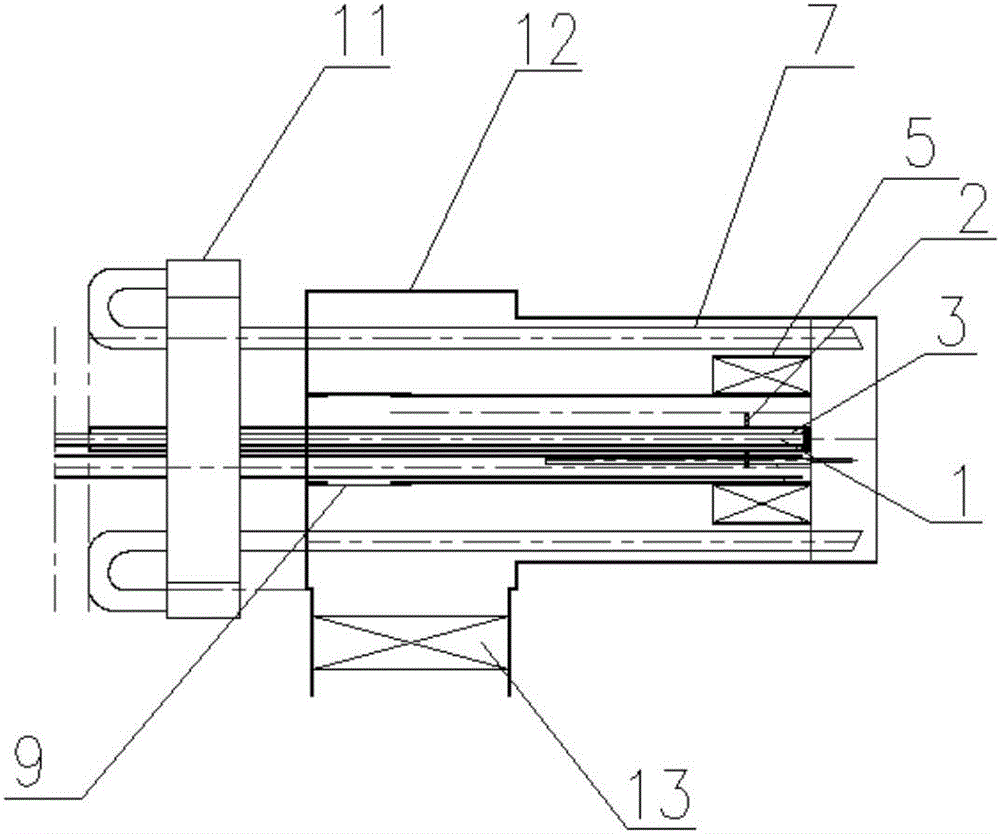
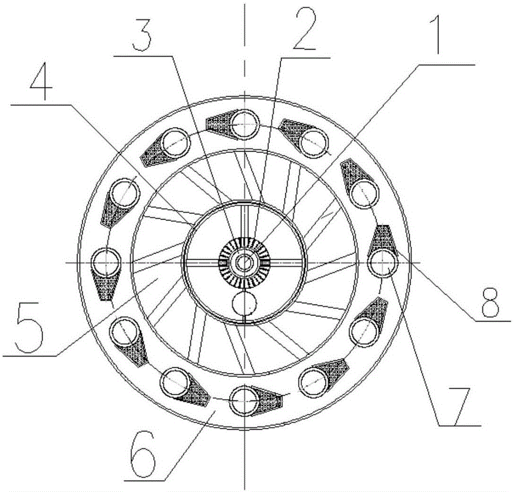
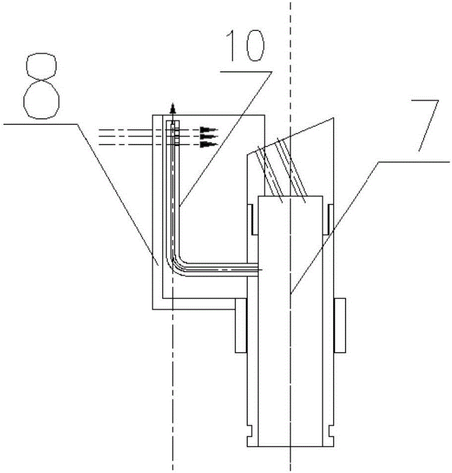
[0023] refer to figure 1 , the ultra-low nitrogen gas burner with gun head self-stabilizing combustion device of the present invention comprises a burner case 12, an inner central air cylinder 1, a central fuel cylinder 3, an outer central air cylinder 4, a swirl air cylinder 5 and several Gas fuel spray gun 7; inner central air cylinder 1, central fuel cylinder 3, outer central air cylinder 4, swirl air cylinder 5 and burner box shell 12 are arranged sequentially from inside to outside, wherein, inner central air cylinder 1 and central fuel cylinder 3 forms an annular gap, an annular outer central wind area is formed between the central fuel cylinder 3 and the outer central air cylinder 4, and an annular swirl wind area is formed between the outer central air cylinder 4 and the swirl air cylinder 5, and the swirl air cylinder 5 An annular direct air area 6 is formed ...
PUM
 Abstract
Description
Claims
Application Information