
Contact state detection method and system for contact deformation member

A technology of contact deformation and contact state, applied in the field of detection, can solve the problems of measurement distortion, inconsistency, low measurement efficiency, etc., to achieve the effect of predicting wear, avoiding unstable readings, and high efficiency

Inactive Publication Date: 2017-05-10
SHANGHAI JIAO TONG UNIV
View PDF7 Cites 0 Cited by
  • Summary
  • Abstract
  • Description
  • Claims
  • Application Information

AI Technical Summary

Problems solved by technology

[0005] Commonly used pressure test methods for contact deformation parts include direct test method of dynamometer and buzzer open circuit test method. The direct test method is to measure the working pressure value of contact deformation parts with a hand-held dynamometer. The method is convenient, but the hand-held test will cause the dynamometer The test position and readings are unstable; the buzzer open circuit test method is to add a buzzer device to the direct test method. Before the tested brush leaves the rotating device, the wires at both ends of the buzzer are short-circuited through the rotating device, and the alarm is always on; In order to eliminate the interference of human factors on the readings of the dynamometer as much as possible, a pressure test system for contact deformed parts driven by a servo motor is designed, but there are still inconsistencies between the measurement point and the contact point, and additional deformation and stress caused by contact measurement. Problems causing measurement distortion and low measurement efficiency
In addition, some people have proposed a pressure measurement method for contact deformation parts based on the small deformation theory of cantilever beams, but it is limited to theoretical research, and the static deformation of contact deformation parts cannot be obtained under working conditions, so that dynamic measurement of contact pressure cannot be performed.
[0006] The current test method is to measure the contact pressure in a static environment, and it is impossible to dynamically detect whether the contact pressure in a period of time under the working state meets the design requirements

Method used


Image

  • Contact state detection method and system for contact deformation member
  • Contact state detection method and system for contact deformation member
  • Contact state detection method and system for contact deformation member

Examples


Embodiment Construction

[0059] The present invention will be described in detail below in conjunction with specific embodiments. The following examples will help those skilled in the art to further understand the present invention, but do not limit the present invention in any form. It should be noted that those skilled in the art can make several changes and improvements without departing from the concept of the present invention. These all belong to the protection scope of the present invention.

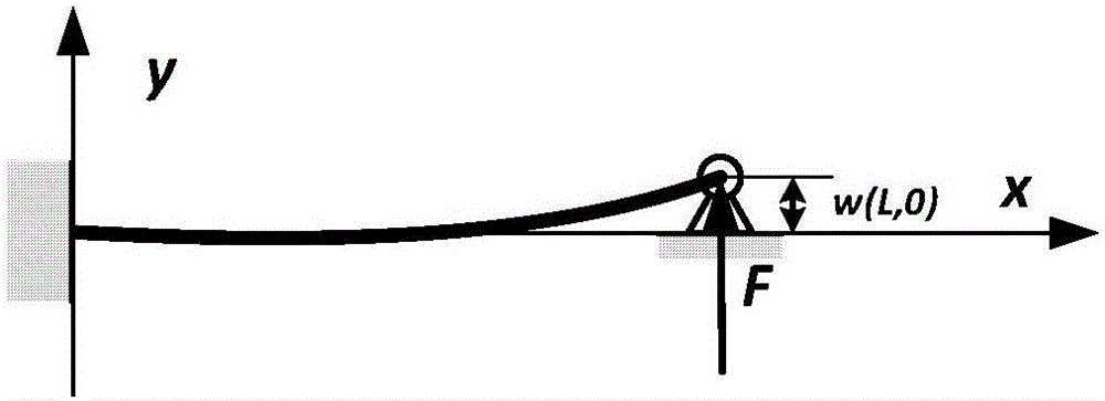
[0060] The invention provides a contact state detection method of a contact deformation part, wherein: the contact deformation part of the rotating device is regarded as a fixed contact beam with one end fixed and one end simply supported, and the simply supported end contacts due to the elastic deformation of the contact deformation part itself. pressure. Such as figure 1As shown, it is a schematic diagram of the principle of the beam model of the contact deformation part; in the figure: the contact d...


PUM


Abstract

The invention provides a contact state detection method and system for a contact deformation member. The contact deformation member of a rotating device is regarded as a constant section beam of which one end is fixed while the other is simply supported, contact pressure is generated via the simply supported end due to elastic deformation of the contact deformation member, vibration response of the contact deformation member is affected by the contact pressure, and the contact pressure can be measured after zero frequency amplitude value of response of any position on a section is detected. Via the method and system, dynamic detection of the contact pressure of the contact deformation member can be realized in a working state or a vibration environment; a contact force time domain course in a period of time is given, whether the contact pressure of the contact deformation member meets work requirements in the working state or the vibration environment can be detected, and wearing conditions of the contact deformation member can be pre-estimated.

Description

technical field [0001] The invention relates to the technical field of detection, in particular to a method and system for detecting a contact state of a contact deformable part. In particular, it is a method for detecting and evaluating the state of contact force and contact reliability under vibration excitation. Background technique [0002] According to the theory of lateral vibration of beams, the contact deformation part of the rotating device can be regarded as a slender beam of equal cross-section with one end fixed and the other simply supported. The lateral vibration equation is: [0003] [0004] Among them, E, I, ρ, and A are the elastic modulus, section moment of inertia, density, and cross-sectional area of ​​the contact deformation part, respectively. w(x,t) is the deflection of the beam, and f(x,t) is the excitation force on the beam. x is the position of the section, and t is the time. The contact pressure of the contact deformation part is directly re...

Claims


Application Information

Patent Timeline
Patent Type & Authority Applications(China)
IPC IPC(8): G01M7/02G01M13/00
Inventor 杨斌堂杨诣坤曹逢雨喻虎
Owner SHANGHAI JIAO TONG UNIV
Learn More