Sampling device for flue gas in close-to-wall zone of boiler water wall

A flue gas sampling and water-cooled wall technology, applied in the direction of sampling devices, sampling, measuring devices, etc., can solve the problems of front-end sampling pipe blockage, small size of water-cooled wall fins, high temperature, etc., to avoid high-temperature corrosion and high operational reliability , long service life effect

Active Publication Date: 2017-05-10
GUODIAN SCI & TECH RES INST +1
View PDF13 Cites 1 Cited by
  • Summary
  • Abstract
  • Description
  • Claims
  • Application Information

AI Technical Summary

Problems solved by technology

[0007] Due to the high furnace temperature, strong radiation heat transfer, small flue gas sampling flow rate, and poor cooling effect, the flue gas sampling probe installed on the water wall, especially the probe inserted into the furnace, is extremely easy to be burned.
Once the flue gas sampling probe is burned, it will lead to poor sealing and leakage, resulting in distortion of measurement results
In addition, the front end of the burnt probe is melted and deformed, which will lead to blockage of the front-end sampling pipeline, and such blockage cannot be solved by conventional backflushing and other measures, resulting in the system not working properly
[0008] (2) The flue gas sampling port and flue gas sampling pipe Louis blockage
Due to the small size of the fins of the water wall (generally width <20mm), the diameter of the opening is generally small, and it is very easy to be blocked by the molten unburned ash in the furnace
In addition, since most of the technical filter devices are installed in the flue gas sampling pipe at a certain distance from the sampling port, although the system is equipped with a backflushing device, the flue gas sampling pipe is still particularly prone to blockage

Method used


Image

  • Sampling device for flue gas in close-to-wall zone of boiler water wall
  • Sampling device for flue gas in close-to-wall zone of boiler water wall
  • Sampling device for flue gas in close-to-wall zone of boiler water wall

Examples


Embodiment 1

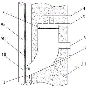
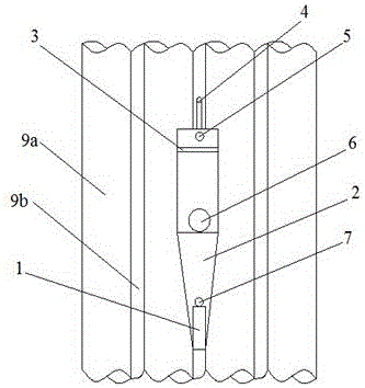
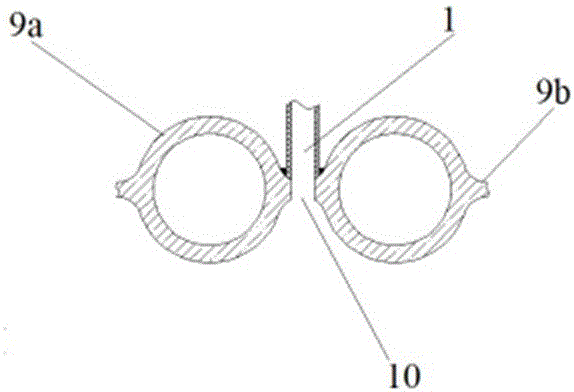
[0037] Such as figure 1 As shown, the flue gas sampling device near the wall of the boiler water wall of the present invention is installed in the thermal insulation layer of the boiler on the backfire side of the fins of the boiler water wall, and is mainly provided with a housing 2, and the housing 2 is provided with a flue gas inlet 1, The flue gas channel 8, the compressed air interface 4 and the flue gas outlet 5, the inner cavity of the shell is the flue gas channel 8, the flue gas inlet 1 and the flue gas outlet 5 are respectively arranged at both ends of the flue gas channel 8, and the flue gas inlet 1 is rectangular The mouth is arranged at the lower end of the shell 2, and the smoke outlet 5 is set at the upper end of the shell 2, and is located on the side opposite to the smoke inlet 1. The device is set in the insulation layer outside the boiler water wall, and a sampling port 10 matching the flue gas inlet 1 is opened on the boiler water wall fin, and the flue gas...

Embodiment 2

[0045] In this example, the bottom surface of the shell adopts a planar structure, and a transition section is provided between the corresponding flue gas channel and the flue gas inlet of the shell. The transition section adopts an arc-shaped structure except for the planar structure at the bottom. The curved structure and the bottom plane jointly form a gradually expanding structure at the lower part of the flue gas channel. All the other parts are the same as embodiment one.

Embodiment 3

[0046] Embodiment 3: In this example, the bottom surface of the housing adopts a planar structure, and the smoke inlet and the smoke outlet are arranged horizontally and directly on both sides of the smoke passage, without forming a gradual expansion structure at the lower part of the smoke passage. All the other parts are the same as embodiment one.


PUM


Abstract

The invention relates to a sampling device for flue gas in a close-to-wall zone of a boiler water wall. The sampling device is provided with a shell; the cavity of the shell is a flue gas channel; and two sides of the flue gas channel are respectively provided with a flue gas inlet and a flue gas outlet. The sampling device is mounted in a heat-insulation layer located at the unexposed-to-fire side of the boiler water wall; a sampling port mating with the flue gas inlet is formed in a fin of the boiler water wall; and the flue gas inlet is mounted on the sampling port via the unexposed-to-fire side of the boiler water wall and communicated with the boiler via the sampling port. The sampling device provided by the invention has the beneficial effect that the problems of burning loss and obstruction of a flue gas sampling probe (gun) and obstruction of a flue gas sampling pipeline are overcome.

Description

technical field [0001] The invention relates to a monitoring and prevention technology for high-temperature corrosion of a water-cooled wall of a coal-fired power plant boiler, in particular to a flue gas sampling device near the wall of the water-cooled wall of a coal-fired boiler furnace, belonging to the technical field of electric power and power engineering. Background technique [0002] In recent years, with increasingly stringent environmental protection requirements, especially the continuous improvement of NOx emission standards for thermal power plants, coal-fired power plants have implemented NOx control technology transformation, and the mainstream technology adopted is low-nitrogen combustion technology + SCR flue gas denitrification technology. Although the strong reduction zone in the furnace formed by the boiler's low-nitrogen combustion technology organization can reduce NOx emissions, it intensifies the high-temperature corrosion of the boiler water wall. ...

Claims


Application Information

Patent Timeline
Patent Type & Authority Applications(China)
IPC IPC(8): G01N1/22
CPCG01N1/2258
Inventor 陈国庆刘建民黄启龙李永生刘铭媛时伟
Owner GUODIAN SCI & TECH RES INST
Why Eureka
Try Eureka