
Device and method for measuring stress and strain in thin plate deformation process under complex stress path

A complex stress, stress-strain technology, applied in the direction of measuring devices, using stable tension/pressure to test the strength of materials, instruments, etc., can solve the problems of inability to accurately and comprehensively describe the deformation characteristics of materials, and the inability to obtain sheet stress and strain data, etc. , to achieve simple and continuous loading process, reliable measurement results, simple and compact structure

Active Publication Date: 2019-04-12
HARBIN INST OF TECH
View PDF7 Cites 0 Cited by
  • Summary
  • Abstract
  • Description
  • Claims
  • Application Information

AI Technical Summary

Problems solved by technology

[0007] The present invention aims to solve the problem that the existing test devices and methods cannot obtain the stress and strain data of the whole process of plate deformation under the general complex path loading conditions, so that the deformation characteristics of the material under the complex stress path cannot be accurately and comprehensively described, and further Provide a device and method for measuring stress and strain in thin plate deformation process under complex stress path

Method used


Image

  • Device and method for measuring stress and strain in thin plate deformation process under complex stress path
  • Device and method for measuring stress and strain in thin plate deformation process under complex stress path
  • Device and method for measuring stress and strain in thin plate deformation process under complex stress path

Examples


Embodiment Construction

[0026] The technical solutions of the present invention will be further described below in conjunction with the accompanying drawings and through specific implementation methods.

[0027] The technical principle adopted by the present invention in order to realize the complex loading path is expressed as follows:

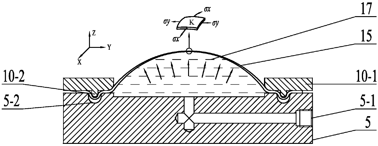
[0028] Depend on image 3 and Figure 4 The force balance of the tiny unit body corresponding to the pole or vertex K on the middle ellipsoid surface can be obtained as follows:

[0029] 2R y δytσ x sin(δx / 2)+2R x δxtσ ysin(δy / 2)=p(R x δx)(R y δy) (1)

[0030] Among them, δx and δy are the lengths of the micro-units corresponding to the pole (vertex) K in the x and y directions, t is the thickness of the micro-units corresponding to K, and R x , R y are the two main radii of curvature along the x-axis and y-axis directions at the pole (vertex) K, respectively, and p is the pressure on the sheet when the sheet is bulging.

[0031] After a simple change, (1...


PUM


Abstract

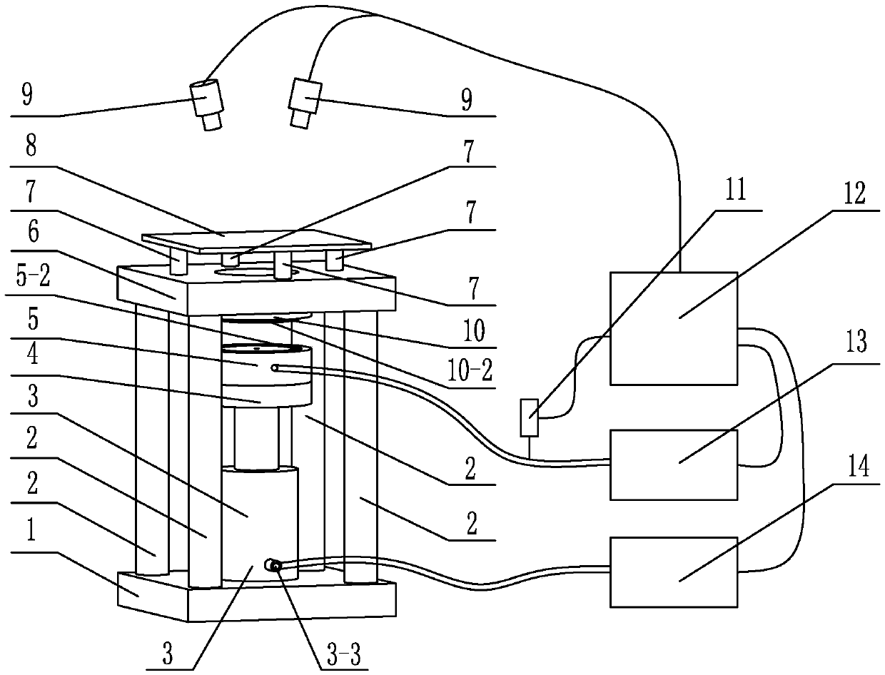
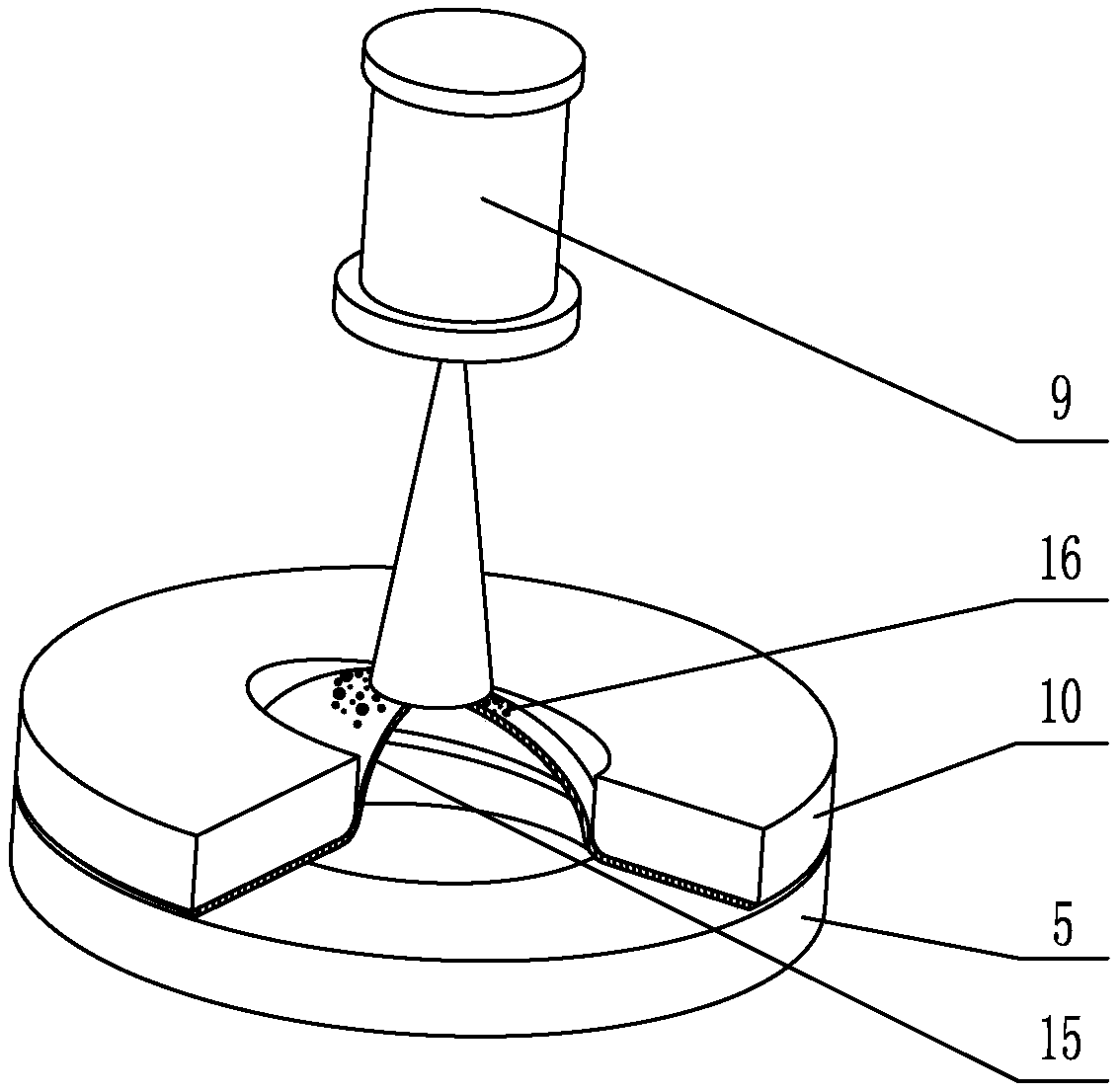
A stress-strain measuring device and method for a thin-plate transformation process under a complex stress path are used for solving the problem that under the complex stress path, deformation characteristics of a material cannot be accurately and totally described, which is caused by existing devices and methods that cannot obtain stress-strain data of the plate transformation process under a general complex path loading condition. The stress-strain measuring device for the thin-plate transformation process under the complex stress path comprises a base, a force application mechanism, a liquid-filling pressing plate, an upper template, a glass plate, a ladder concave die, a pressure sensor, a control system, a liquid-filling pressure system, a power system, a CCD camera, and a plurality of supporting blocks and connection rods. The measuring method includes the following steps: (1) manufacturing the ladder concave die and cutting the thin-plate; (2) conducting assembly and liquid filling; (3) conducting plate bulging; (4) acquiring stress-strain information; (5) disassembling the device and saving experimental data. The stress-strain measuring device and method for the thin-plate transformation process under the complex stress path is used for thin-plate stress-strain measurements under the complex stress path.

Description

technical field [0001] The invention relates to a stress-strain measuring device and method in the deformation process of a thin-walled plate, in particular to a stress-strain measuring device and method in a thin-walled plate deformation process under a complex stress path. Background technique [0002] With the requirement of high reliability and long service life for high-tech weaponry, it is urgent to use integral components instead of traditional tailor-welded assembly structures. In order to realize the forming of such complex thin-walled integral components, it is often necessary to go through a complex deformation process. The changes in the shape, size and boundary conditions of the blank during the deformation of the sheet will lead to changes in the stress path, and the loading path is nonlinear. [0003] The actual thin-walled sheet has a certain degree of anisotropy, and will show different deformation characteristics and formability under different loading path...

Claims


Application Information

Patent Timeline
Patent Type & Authority Patents(China)
IPC IPC(8): G01N3/10
CPCG01N3/10G01N2203/0003G01N2203/0017G01N2203/0048G01N2203/0075G01N2203/0272G01N2203/0641
Inventor 何祝斌朱海辉张坤苑世剑
Owner HARBIN INST OF TECH
Learn More