Spaceflight servo motor variable working condition dynamic loading system and spaceflight servo motor variable working condition dynamic loading method

A dynamic loading, servo motor technology, applied in the direction of motor generator testing, etc., to eliminate the influence of excess force and accurately load

Inactive Publication Date: 2017-05-10
BEIJING RES INST OF PRECISE MECHATRONICS CONTROLS +1
View PDF4 Cites 8 Cited by
  • Summary
  • Abstract
  • Description
  • Claims
  • Application Information

AI Technical Summary

Problems solved by technology

[0005] Aiming at the typical working conditions of aerospace servo motors with high-frequency, large-scale and frequent acceleration and deceleration, the present invention provides a dynamic loading system and loading method for aerospace servo motors under variable working conditions. The loading system and loading method solve the problem of high-frequency sinusoidal The problem of redundant force compensation during motion eliminates the redundant force of the motor under test on the loading motor and ensures the accuracy of the loading torque

Method used


Image

  • Spaceflight servo motor variable working condition dynamic loading system and spaceflight servo motor variable working condition dynamic loading method
  • Spaceflight servo motor variable working condition dynamic loading system and spaceflight servo motor variable working condition dynamic loading method
  • Spaceflight servo motor variable working condition dynamic loading system and spaceflight servo motor variable working condition dynamic loading method

Examples


Embodiment Construction

[0029] The present invention will be described in further detail below in conjunction with the accompanying drawings.

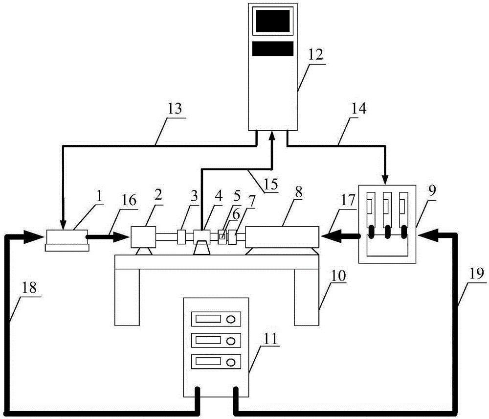
[0030] Such as figure 1 As shown, a dynamic loading system for aerospace servo motors under variable working conditions provided by the present invention, the system includes a tested motor driver 1, a tested motor 2, a first coupling 3, a torque sensor 4, a second coupling 5, acceleration sensor 6, electric slip ring 7, loading motor 8, loading driver 9, tooling stand 10, DC power supply 11, control cabinet 12, position instruction signal line 13, loading instruction signal line 14, torque speed acquisition signal line 15 , the signal line 16 of the motor driver under test and the motor under test, the signal line 17 of the loading driver and the loading motor, the first power source 18 and the second power source 19 . The DC power supply 11 supplies power for the dynamic loading system, and the motor under test 2 is coaxially connected with the loading mot...


PUM


Abstract

The invention belongs to the spaceflight servo motor testing field, to be specific, discloses a spaceflight servo motor variable working condition dynamic loading system and a spaceflight servo motor variable working condition dynamic loading method. The spaceflight servo motor variable working condition dynamic loading system comprises a tested motor driver, a tested motor, a first coupler, a torque sensor, a second coupler, an acceleration sensor, an electric slip ring, a loading motor, a loading driver, a direct current power supply, and a control cabinet. The spaceflight servo motor variable working condition dynamic loading method comprises steps that the control cabinet is used to set the motion form and the load parameter of the tested motor; the control cabinet is used to transmit a position instruction signal to the detected motor driver, and is used to control the motion form of the tested motor; during the variable working condition motion of the tested motor, the control cabinet is used to transmit a loading instruction signal to the loading motor driver; a deviation signal of loading torque and feedback torque is calculated by a PI control algorithm to acquire a loading control signal, which is transmitted to the loading motor driver, and then redundant force elimination is realized. The loading system and the loading method are used to eliminate the redundant force of the tested motor applied to the loading motor, and therefore the accuracy of the loading torque is guaranteed.

Description

technical field [0001] The invention belongs to the field of testing servo motors for aerospace, and in particular relates to a dynamic loading system and a loading method for variable working conditions of servo motors for aerospace. Background technique [0002] Servo motors for aerospace, as the key power components of the electromechanical servo system, receive position commands from the control system, drive air rudders or nozzle loads, and generate the required control force to control the stable flight of the gliding vehicle. The loads of the electromechanical servo system mainly include inertial loads, elastic loads, and frictional loads. The inertial loads are torques that have nothing to do with the rotor position and speed, but are related to the direction of the speed. They are only generated during the dynamic change of the servo motor; elastic loads are a A torque proportional to the rotor angle; friction load is a torque proportional to the rotor speed. [00...

Claims


Application Information

Patent Timeline
Patent Type & Authority Applications(China)
IPC IPC(8): G01R31/34
CPCG01R31/34
Inventor 曾广商黄玉平闫海媛郭喜彬
Owner BEIJING RES INST OF PRECISE MECHATRONICS CONTROLS
Why Eureka
Try Eureka