
Method and circuit for improving FID signal frequency measurement precision based on quantized time delay method

A technology of signal conditioning circuit and high-frequency oscillation circuit, which is applied in the direction of the magnitude/direction of the magnetic field, measuring device, and measuring magnetic variables, etc. It can solve the problems of affecting the accuracy of frequency measurement, low signal-to-noise ratio, and poor signal quality. Reduce the cost of transformation, improve the accuracy of frequency measurement, and overcome the effect of complex hardware

Active Publication Date: 2017-05-10
CHINA UNIV OF GEOSCIENCES (WUHAN)
View PDF10 Cites 10 Cited by
  • Summary
  • Abstract
  • Description
  • Claims
  • Application Information

AI Technical Summary

Problems solved by technology

[0004] However, the first method uses a comparator and CPLD for measurement, and does not consider error compensation for the asynchronous part of the clock edge; the second method uses the traditional hardware measurement method, because the FID signal decays to the later stage, If the signal-to-noise ratio is too low, there will inevitably be counting errors; the third method uses the algorithm of ADC+FFT+CZT to eliminate the counting errors caused by the low signal-to-noise ratio, but it will also affect the frequency measurement due to the deterioration of the signal quality. precision

Method used


Image

  • Method and circuit for improving FID signal frequency measurement precision based on quantized time delay method
  • Method and circuit for improving FID signal frequency measurement precision based on quantized time delay method
  • Method and circuit for improving FID signal frequency measurement precision based on quantized time delay method

Examples


Embodiment Construction

[0039] In order to make the purpose, technical solution and advantages of the present invention clearer, the embodiments of the present invention will be further described below in conjunction with the accompanying drawings.

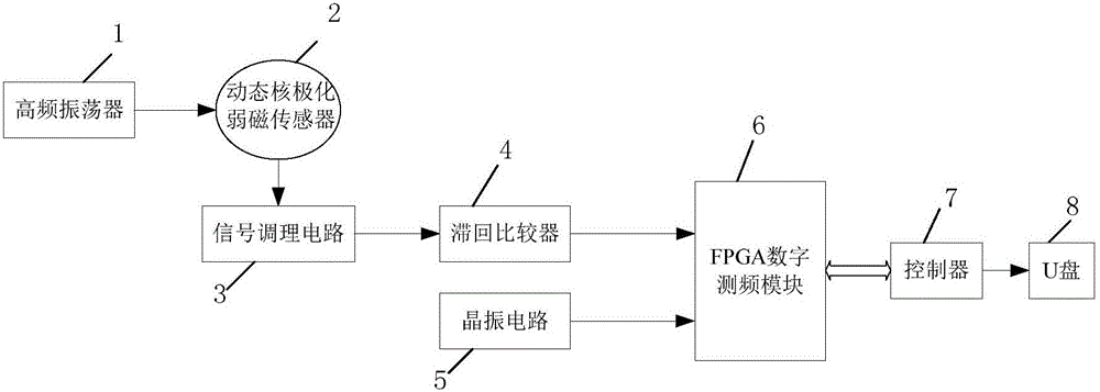
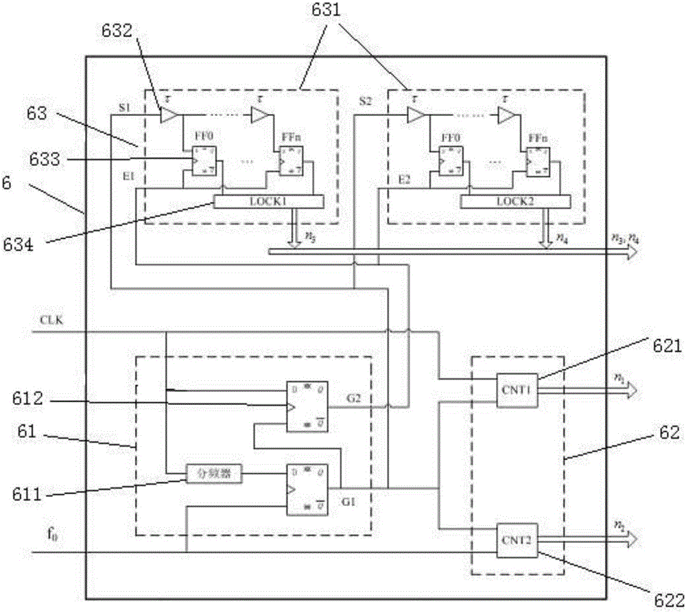
[0040] Please refer to figure 1 , the embodiment of the present invention provides a circuit for improving the frequency measurement accuracy of FID signals based on the quantization delay method, including a high-frequency oscillation circuit 1, a dynamic nuclear polarization weakening sensor 2, a signal conditioning circuit 3, and a hysteresis comparator 4 , crystal oscillator circuit 5, FPGA digital frequency measurement module 6, controller 7 and storage unit 8, in one embodiment, described storage unit is U disk, the input end of dynamic nuclear polarization weakening magnetic sensor 2 connects high-frequency oscillation circuit 1. The high-frequency oscillation circuit 1 excites the dynamic nuclear polarization weak magnetic sensor 2 to generate th...


PUM


Abstract

The invention provides a method for improving the FID signal frequency measurement precision based on a quantized time delay method. The frequency measurement method uses the equal-precision frequency measurement principle and adopts a precision measurement method with 'rough measurement+fine measurement', the 'fine measurement' makes time compensation for the nonsynchronization of the standard clock edge and the measured signal edge by means of the quantized time delay method. The quantized time delay method adopts the method of digital time interpolation and overcomes the defect of complex hardware of a simulation interpolator, subsystems in a frequency measurement module are integrated in an FPGA, so that the circuit is easy realize and high in reliability, the frequency measurement resolution depends on the time-delay amount of a unit time-delay unit, the frequency measurement precision of a magnetometer is greatly improved to a large extent, and a corresponding device can be selected on the set object basis, and the improvement cost is reduced. The invention further includes a circuit for improving the FID signal frequency measurement precision based on the quantized time delay method.

Description

technical field [0001] The invention relates to the technical field of earth weak magnetic field measurement, in particular to a method and a circuit for improving the frequency measurement accuracy of FID signals based on a quantization time delay method. Background technique [0002] The dynamic nuclear polarization magnetometer has the characteristics of low power consumption, no dead zone, and high sensitivity. It has been widely used in the fields of geophysical magnetic exploration, earth science research, anti-submarine, and satellite magnetic survey. The dynamic nuclear polarization magnetometer usually includes two resonance systems: electron spin resonance and nuclear magnetic resonance. The instrument uses the electron spin resonance generated by the radio frequency electromagnetic field and the coupling relaxation of the two resonance systems to convert the energy of the electron spin resonance into Transferred to nuclear magnetic resonance, thereby improving the...

Claims


Application Information

Patent Timeline
Patent Type & Authority Applications(China)
IPC IPC(8): G01R33/02G01V3/40
CPCG01R33/0029G01R33/02G01V3/40Y02E30/30
Inventor 葛健董浩斌邱香域刘欢罗望李晗
Owner CHINA UNIV OF GEOSCIENCES (WUHAN)
Learn More