Spreadlight lens and edge-lit backlight module containing spreadlight lens

An edge-type backlight and polarizing lens technology, applied in the field of edge-type backlight modules, can solve the problems of development limitation, light energy loss, low brightness of the display screen, etc., to solve the problem of uneven brightness, high brightness uniformity, production The effect of cost advantage

Inactive Publication Date: 2017-05-10
NINGBO ZHENGTE OPTICAL ELECTRIC APPLIANCE
View PDF7 Cites 8 Cited by
  • Summary
  • Abstract
  • Description
  • Claims
  • Application Information

AI Technical Summary

Problems solved by technology

At present, the backlight modules of display devices can be divided into two types: side-type and direct-type. Compared with side-type backlight modules, direct-type backlight modules do not need to be equipped with light guide plates, and because of the advantage of low price, deep It is popular with consumers, but the LED light bar in the direct-lit backlight module needs to install an optical lens outside the LED light-emitting chip. Only under the condition of a large mixing distance (OD) can the light emitted by the LED light-emitting chip Mix evenly, so that the development of direct-lit backlight modules is greatly restricted under the demand trend of thinner and lighter display devices
[0003] At the same time, in the traditional direct-type backlight module, the LED is a Lambertian light source, and the optical lens (TV lens) installed on the LED has rotational symmetry in structure, so the light emitted by the LED is diffused by the TV lens, and the formed light spot has a The circular light spot with rotational symmetry, and the direct-lit backlight module and its display device generally have a front shape with an aspect ratio of about 4:3 or 16:9. The mismatch between the light spot and the shape will inevitably cause the corners of the backlight module And the uneven brightness of the central area affects the quality of the viewing picture
In the traditional side-type backlight module, the light emitted by the LED needs to be scattered by the dots of the light guide plate and refracted by the light guide plate, so that the LED light source entering the side light is converted into a surface light source output from the front. The multiple scattering of the dots and the light guide plate Refraction causes serious loss of light energy, resulting in low light efficiency of the side-lit backlight module and low brightness of the display screen

Method used


Image

  • Spreadlight lens and edge-lit backlight module containing spreadlight lens
  • Spreadlight lens and edge-lit backlight module containing spreadlight lens
  • Spreadlight lens and edge-lit backlight module containing spreadlight lens

Examples


Embodiment 1

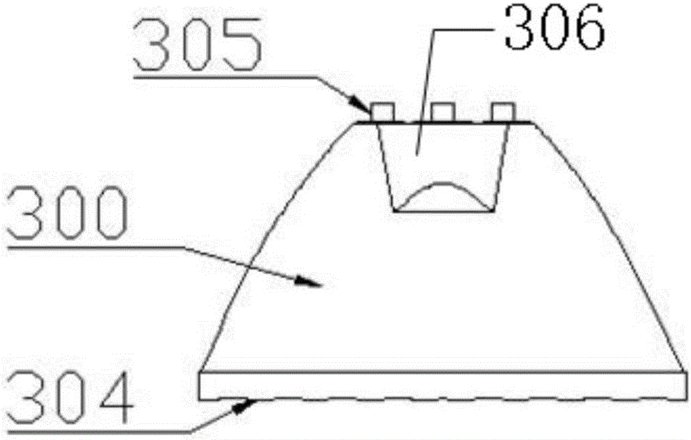
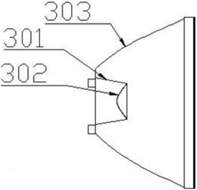
[0047] A polarizing lens such as figure 1 , figure 2 and image 3 As shown, including a mirror body, the mirror body includes an incident side surface 301, an incident top surface 302, a reflective surface 303, and an exit surface 304, and the material of the polarizing lens 300 is PMMA; the inner concave portion 306 formed by the incident side surface 301 and the incident top surface 302 is rotationally symmetrical , the light source is located on the axis of rotation of the inner concave portion 306; the reflective surface 303 is non-rotationally symmetrical, that is, the meridional axis and the sagittal axis of the polarizing lens 300 do not coincide; the incident side 301 is connected to the reflective surface 303, and the reflective surface 303 is connected to the outgoing surface 304 The exit surface 304 of the polarizing lens 300 can be a convex surface, a concave surface, a scale surface or a smooth surface, preferably a scale surface; the draft angle of the incident...

Embodiment 2

[0049] Side-entry backlight module, including body 1, such as Figure 4 as shown, Figure 4 It is a structural schematic diagram of the 32-inch backlight module provided by Embodiment 2 of the present invention. The main body includes: cavity 104, reflective paper, light bar 106, diffusion plate 102 and optical film 101; the cavity 104 is the overall shape structure of the backlight module, and the reflective paper is tightly attached to the inside of the cavity 104 by double-sided adhesive The cavity on the bottom surface is attached with reflective paper 103 and the upper part of the light bar reflective paper 105 attached to the upper part of the cavity 104, and the cavity attached reflective paper 103 and the bottom surface of the cavity 104 have the same shape, and the upper part of the light bar reflective paper 105 is located on the light bar 106 Above, the length of the reflective paper 105 on the upper part of the light bar is greater than or equal to the length of t...

Embodiment 3

[0072] Such as Figure 13 as shown, Figure 13 It is a schematic diagram of the structure of the 55-inch backlight module provided by Embodiment 3 of the present invention. The difference from Embodiment 2 is that

[0073] The 55-inch backlight mode light bar 106 of the embodiment of the present invention needs two, and each is installed on the opposite inner wall of the cavity 104 .

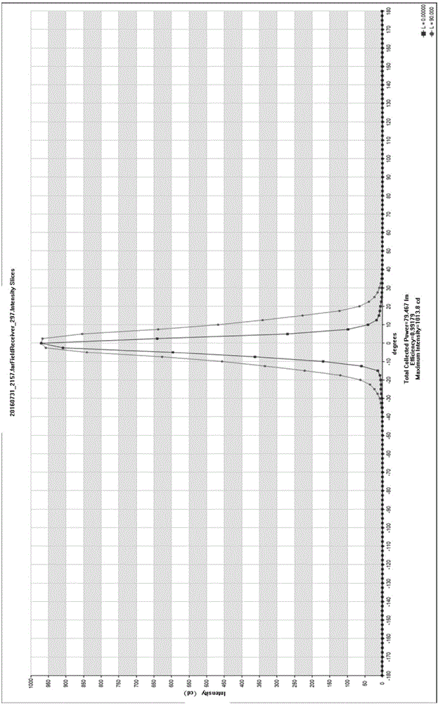
[0074] The mixing distance OD value of the embodiment of the present invention is 20mm, that is, the maximum distance from the bottom surface of the diffusion plate 102 to the bottom surface of the cavity 104 is 20mm, and the minimum distance is 8.2mm; the model of the CSP light source 400 is EPISTAR 1010, and the CSP light source 400 and polarizing lens on the single light bar 106 The number of 300 is 42, and the distance between the CSP light source 400 is 29mm, the outer size of the polarizing lens 300 is 20mm*20mm*11.2mm, the material of the reflective paper 103 and 105 is RA8E, and the thi...


PUM

PropertyMeasurementUnit
angleaaaaaaaaaa
refractive indexaaaaaaaaaa

Abstract

The invention discloses a spreadlight lens comprising a lens body. The lens body comprises an incident surface, a reflecting surface and an emergent surface. The incident surface comprises an incident top surface and an incident side surface, the incident top surface is connected with the incident side surface to form a rotationally symmetric recess part, and a light source is arranged on the rotation axis of the recess part; the reflecting surface is not rotationally symmetric. The invention further discloses an edge-lit backlight module comprising a body. The body comprises a cavity, reflecting paper, a light bar, a diffuser plate and a optical film. The reflecting paper comprises attaching cavity reflecting paper which is attached to the bottom face in the cavity and light bar upper reflecting paper arranged at the top of the cavity. The light bar comprises a PCB substrate, a CSP light source and the spreadlight lens, wherein the PCB substrate, the CSP light source and the spreadlight lens are arranged on the inner side wall of the cavity. By the adoption of a special secondary light distribution spreadlight lens edge-lit mode and the arrangement of the reflecting paper with a special cambered surface type, the effects of being high in brightness uniformity, high in luminous efficiency and lightening and thinning in backlight module are achieved.

Description

technical field [0001] The invention relates to the field of liquid crystal display, in particular, the invention relates to a polarized lens and a side-entry backlight module comprising the same. Background technique [0002] In the field of existing liquid crystal displays, since the liquid crystal molecules themselves do not have the ability to emit light, an external light source is required to obtain the display screen in the existing liquid crystal display. At present, light-emitting diodes are mostly used as light sources. LED light source is extended to surface light source output. At present, the backlight modules of display devices can be divided into two types: side-type and direct-type. Compared with side-type backlight modules, direct-type backlight modules do not need to be equipped with light guide plates, and because of the advantage of low price, deep It is popular with consumers, but the LED light bar in the direct-lit backlight module needs to install an ...

Claims


Application Information

Patent Timeline
Patent Type & Authority Applications(China)
IPC IPC(8): G02F1/13357
CPCG02F1/1336G02F1/133605G02F1/133611G02F1/133615G02F1/133607
Inventor 章奇
Owner NINGBO ZHENGTE OPTICAL ELECTRIC APPLIANCE
Why Eureka
Try Eureka