Apparatus and method of calibrating particle position detector in dual-beam trap system

An optical trap system and detector technology, applied in the fields of precision measurement and optical engineering, to achieve the effect of strong practicability, wide application range and simple structure

Active Publication Date: 2017-05-10
NAT UNIV OF DEFENSE TECH
View PDF6 Cites 11 Cited by
  • Summary
  • Abstract
  • Description
  • Claims
  • Application Information

AI Technical Summary

Problems solved by technology

These two Gaussian laser beams are called trapping lasers

Method used


Image

  • Apparatus and method of calibrating particle position detector in dual-beam trap system
  • Apparatus and method of calibrating particle position detector in dual-beam trap system
  • Apparatus and method of calibrating particle position detector in dual-beam trap system

Examples


Embodiment Construction

[0014] An embodiment of the present invention will be described in detail below in conjunction with the accompanying drawings, but the protection scope of the present invention should not be limited thereby.

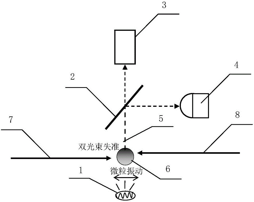
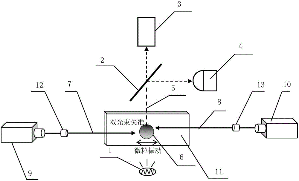
[0015] Such as figure 1 As shown, a device for calibrating particle position detectors using beam misalignment in a dual-beam optical trap is composed of an illumination source 1, an optical beam splitter 2, an image sensor 3 and a position detector 4, a capture laser 7 and a capture laser 8 Opposite propagation forms an optical trap to capture particles 6, and the optical beam splitter 2 divides the illumination beam 5 containing scattered laser light into two: one path of light enters the image sensor 3 for real-time monitoring of the particle position; the other path of light enters the position detection The device 4 is used for real-time monitoring of the scattered photovoltage signal. If the trapping laser 7 and the trapping laser 8 are misaligned, the particles 6...


PUM


Abstract

The invention relates to an apparatus and a method of calibrating a particle position detector in a dual-beam trap system, and belongs to the optical engineering field and the precision measurement technology field. The apparatus comprises an illumination light source, a light beam splitter, a camera and a position detector. Two beams of captured laser spread toward each other to form light trap captured particles. The light beam splitter divides an optical path into two routes: one route of light enters an image sensor to monitoring positions of the particles in real time, and the other route of light enters the position detector to monitor diffusion light voltage signals in real time. The two beams of the captured laser are made to be out of alignment, displacement changes of the particles are measured by the image sensor, and voltage signal changes caused by displacement of the particles are obtained through the position detector. Characteristic coupling is conducted on the displacement changes of the particles and voltage changes of the position detector, so a corresponding relationship between the displacement changes of the particles and the voltage changes of the position detector can be obtained, calibration coefficients can be obtained, and calibration can be completed. The apparatus has the advantages of simple structure, high measuring precision, high practicality, etc. Moreover, the apparatus and the method are not limited to particle types and sample room structures, and are wide in application range.

Description

technical field [0001] The invention relates to a device and method for calibrating a position detector by using particle vibration caused by misalignment of beams in a double-beam optical trap system, belonging to the fields of optical engineering and precision measurement technology. Background technique [0002] Two Gaussian laser beams propagating in opposite directions can form a double-beam optical potential well capable of confining micron-scale particles, referred to as a double-beam optical trap. Dual-beam optical traps can realize multiple functions such as optical trapping, optical traction, optical stretching, and photo-induced rotation, and have broad application prospects. [0003] The detection of the particle position is a key problem to be solved in the application of the optical trap system. One of the commonly used methods is to use the position detector to detect the position of the trapped particles in the optical trap. Scattered light from the particle...

Claims


Application Information

Patent Timeline
Patent Type & Authority Applications(China)
IPC IPC(8): G21K1/00G21K1/10
CPCG21K1/00G21K1/10
Inventor 肖光宗熊威韩翔邓丹杨开勇罗晖
Owner NAT UNIV OF DEFENSE TECH
Why Eureka
Try Eureka