

High-temperature fusant battery apparatus and preparation process thereof
A battery device and high-temperature melt technology, applied in secondary batteries, battery pack parts, battery boxes/jackets, etc., can solve problems such as corrosion of high-temperature insulating and sealed batteries, and achieve a reduction in production cycle, good performance, and cost reduction. Effect
- Summary
- Abstract
- Description
- Claims
- Application Information
AI Technical Summary
Problems solved by technology
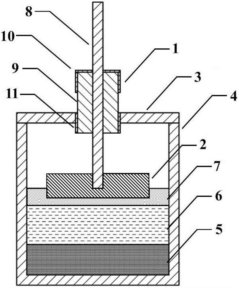
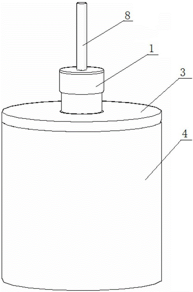
Method used
Image

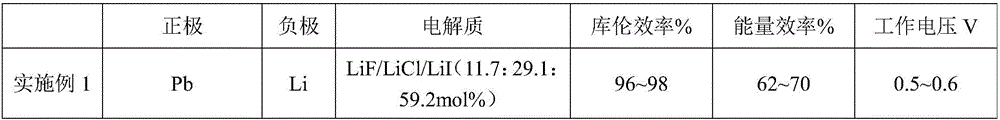
Examples
Embodiment 3
[0063] The preparation process of the liquid metal battery adopted in embodiment 3 is as follows:
[0064] 1) Put Sb pellets into a mold and heat to melt. The heating process is as follows: 5°C / min to 800°C, heat preservation for 10h, and then naturally cool to room temperature. The whole process is carried out in an absolute vacuum or high-purity argon environment less than 0.1Pa.
[0065] 2) the mixed MgCl 2 , NaCl and KCl electrolyte powders were put into a mold and heated and melted. The heating process was as follows: the temperature was raised to 450°C at a rate of 1°C / min, kept for 15 hours, and then naturally cooled to room temperature to obtain the battery electrolyte material. The whole process is carried out in an absolute vacuum or high-purity argon environment less than 0.1Pa.
[0066] 3) Put the metal Mg into the mold and heat and melt it. The heating process is as follows: the temperature is raised to 800° C. at 5° C. / min, and the temperature is kept for 3 to ...
Embodiment 6
[0073] The preparation process of the liquid metal battery adopted in embodiment 6 is as follows:
[0074] 1) Put the metal Te into the mold and heat and melt it. The heating process is as follows: the temperature is raised to 800°C at 5°C / min, kept for 20 hours, and then naturally cooled to room temperature. The whole process is carried out in an absolute vacuum of less than 0.1Pa or in high-purity argon.
[0075] 2) Put the mixed NaF, NaCl and NaI electrolyte powders into a mold and heat and melt them. The heating process is to raise the temperature to 600°C at 1°C / min, keep it warm for 20h, and then cool it down to room temperature naturally. The whole process is carried out in an absolute vacuum or high-purity argon environment less than 0.1Pa.
[0076] 3) Put the metal Na into the mold and heat and melt it. The heating process is as follows: the temperature is raised to 400° C. at 5° C. / min, and the temperature is kept for 3 to 5 hours. The anode current collector was s...
PUM
| Property | Measurement | Unit |
|---|---|---|
| Thickness | aaaaa | aaaaa |
Abstract
Description
Claims
Application Information