
Electric cable stripper

A technology of wire strippers and cables, applied in the direction of line/collector components, circuits, electrical components, etc., can solve the problems of crank linkage mechanism exposure, increase device weight, increase battery capacity and volume, etc., to ensure continuous performance and reliability, reduced space requirements, reduced volume and weight

Active Publication Date: 2018-06-29
LIVE WORKING CENT OF STATE GRID HUNAN ELECTRIC POWER +2
View PDF8 Cites 0 Cited by
  • Summary
  • Abstract
  • Description
  • Claims
  • Application Information

AI Technical Summary

Problems solved by technology

Although the above-mentioned technical solution solves the problem of high labor intensity of manual peeling, the transmission ratio of the crank-link mechanism is relatively small, the required motor power is larger, and the working time is long. Increasing the working time will inevitably increase the battery capacity and volume, and further increase the weight of the entire device , reduced portability
And there are still some deficiencies in its use, such as: the integrated design of the control device and the peeling device is not suitable for use in live work; Security risks

Method used


Image

  • Electric cable stripper
  • Electric cable stripper
  • Electric cable stripper

Examples


Embodiment Construction

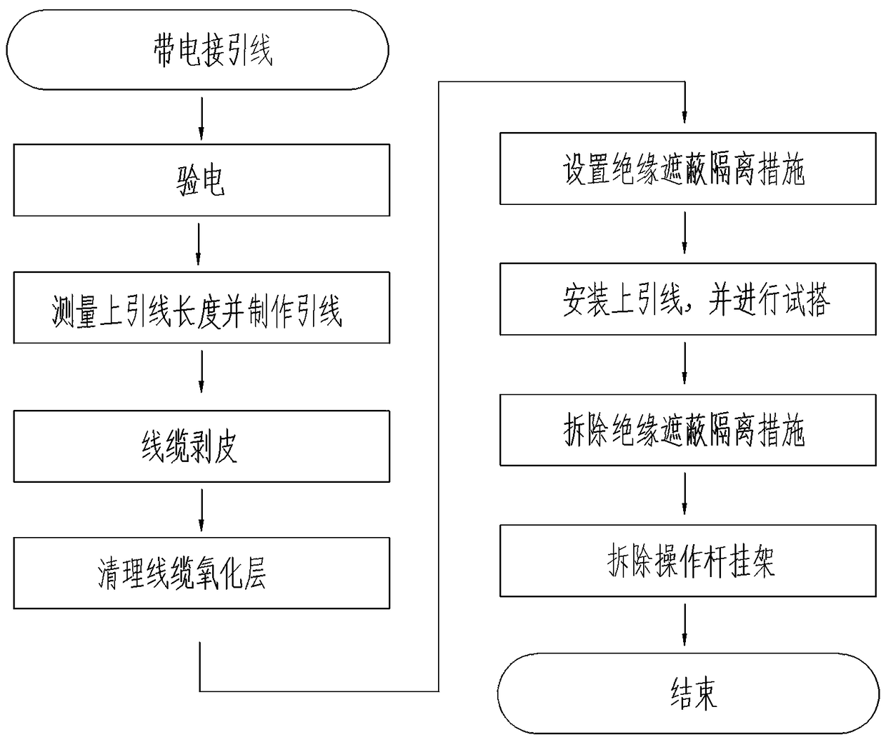
[0027] Such as figure 1 As shown, this preferred embodiment performs the live connection of the power insulated cable through the following steps:

[0028] 1. Enter the live working area and check the electricity. The No. 1 and No. 2 electricians have been approved by the person in charge of the work and wear insulating protective equipment. The No. 1 electrician shall carry the insulation transfer rope, climb the pole to a suitable working position, and hang the insulation transfer rope. No. 2 electrician installs the operating pole hanger; the electrician on the pole uses an electroscope to conduct electrical inspection on the live body and cross arm to confirm that there is no leakage; the requirements during the electrical inspection process: 1) Insulating tools and materials should be transferred up and down. Rope; 2) Correct use of insulated ropes (when transferring tools and instruments, the back of the operator should not be carried, and the insulated tail rope should not ...


PUM


Abstract

The invention discloses a novel electrified lead connection method and an electric wire stripper for cables. The method comprises the following steps of: climbing on a pole by an electrician to affirm that no electric leakage phenomenon exists, measuring and manufacturing leads, measuring the lengths of leads on three phases by the electrician on the pole by using an insulating electricity inspection and distance measurement integrated rod, and manufacturing an upper lead by an electrician on the ground; carrying out stripping according to a sequence of A phase, B phase and C phase by using the electric wire stripper for cables, cleaning a cable oxidation layer at a hook-up wire clip, setting a three-phase insulating, shielding and isolating measure; respectively transferring an insulating operation rod and an insulating and shielding tool onto the pole by the electrician on the pole under the coordination of the electrician on the ground; carrying out insulating and shielding by the electrician on the pole by utilizing the insulating operation rod according to the sequence of B phase, C phase and B phase; mounting the upper lead on an upper pile head of a drop-out fuse, carrying out test lap joint, carrying out lap joint on branch line leads of B phase, C phase and A phase in sequence; dismantling the three-phase insulating, shielding and isolating measure, carrying out dismantling by the electrician on the pole according to the sequence of B phase, B phase and A phase; checking that operation requirements are satisfied by the electrician on the pole and then returning to the ground to complete electrified lead connection, so as to ensure the continuity and reliability of power supply.

Description

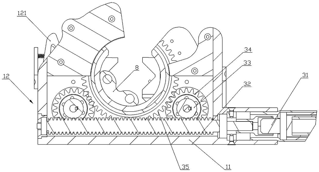
Technical field [0001] The invention relates to a tool for connecting lead wires, in particular to an electric wire stripper for cables. Background technique [0002] At present, most of the cable sheathing is stripped by manual operation tools, which rely on manual application of external force to rotate the manual operation tool along the cable, and strip the cable sheath using a shaped stripping tool. Because the external force for rotating the tool and the action of pressing the knife are manually applied, the labor intensity is high, the work efficiency is low, and it is inconvenient to realize the automatic operation. At the same time, it also increases the insecurity of manual operation and poses safety risks. [0003] The patent application number 201020531056.7 discloses a cable stripper. The stripper adopts an electric drive, and uses the force of a geared motor to drive the blade to rotate around the cable through a crank connecting rod mechanism to achieve a circumcisio...

Claims


Application Information

Patent Timeline
Patent Type & Authority Patents(China)
IPC IPC(8): H01R43/28H02G1/12
CPCH01R43/28H02G1/1221H02G1/1241
Inventor 刘夏清邹德华李稳牛捷胡弘莽唐力朱亮宁昕
Owner LIVE WORKING CENT OF STATE GRID HUNAN ELECTRIC POWER
Learn More