

Active discharge control circuit of motor controller of electric vehicle and controller
A motor controller and discharge control technology, which is applied in the direction of AC motor control, electric vehicles, battery circuit devices, etc., can solve problems such as increased controller burden, abnormal torque, and discharge failure, and achieve simple and convenient control, increased reliability, The effect of reducing the burden
- Summary
- Abstract
- Description
- Claims
- Application Information
AI Technical Summary
Problems solved by technology
Method used
Image

Examples
Embodiment 1
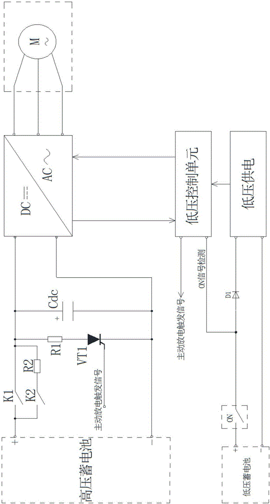
[0022] refer to figure 1 , an active discharge control circuit for an electric vehicle motor controller, including a discharge main circuit and a discharge control circuit; the discharge main circuit includes a discharge resistor R1 and a thyristor VT1 connected in series; the discharge control circuit includes a discharge control module and an ignition switch ON signal detection branch; the output end of the ignition switch ON signal detection branch is connected to the discharge control module; the discharge control module is connected to the thyristor VT1 and controls the switch of the thyristor VT1. The discharge control module is a processor.
[0023] The following processors are discharge control modules, and the ON signal detection mechanism has the following two methods:
[0024] The first type: If isolation is required for detection, an isolation device such as an optocoupler needs to be used between the ON signal and the processor to send the signal to the processor...
Embodiment 2
[0027] refer to figure 1 , an electric vehicle motor controller, comprising a high-voltage battery, a low-voltage power supply circuit, an inverter circuit, a low-voltage battery, a DC capacitor Cdc, an ignition switch ON, a discharge main circuit and a low-voltage control unit.
[0028] The inverter circuit includes an inverter, a positive DC bus and a negative DC bus. The inverter is connected to the positive pole of the high-voltage battery through the positive DC bus, and the inverter is connected to the negative pole of the high-voltage battery through the negative DC bus. The DC capacitor Cdc is connected between the positive DC bus and the negative DC bus. The discharge main circuit includes a discharge resistor R1 and a thyristor VT1 connected in series, and the discharge resistor R1 and the thyristor VT1 are connected between the positive DC bus and the negative DC bus.
[0029] The low-voltage battery supplies power to the low-voltage control unit through the low-vo...
PUM
 Abstract
Description
Claims
Application Information