System and method for determining correction values of absolute position signals of hybrid photoelectric encoder

A photoelectric encoder, absolute position technology, applied in the direction of electromechanical devices, electrical components, electric components, etc., can solve the problems of large influence on the starting performance of the servo motor, affecting the control performance of the servo system, low precision of the absolute position signal, etc. The effect of promoting use, saving manpower and material resources, and low cost

Inactive Publication Date: 2017-05-10
XIAN UNIV OF SCI & TECH
View PDF6 Cites 7 Cited by
  • Summary
  • Abstract
  • Description
  • Claims
  • Application Information

AI Technical Summary

Problems solved by technology

[0003] Like other types of sensors, there are deviations in both the absolute position signal and the relative position signal in the hybrid photoelectric encoder. Due to the low accuracy of the absolute position signal and the large deviation range, this has a great impact on the starting performance of the servo motor; When absolute position signals are used for position and speed monitoring or control in operation control, corresponding errors will also be introduced, which will affect the control performance of the servo system
Therefore, it is necessary to calibrate and calibrate the absolute position signal. At present, the absolute position signal of the hybrid photoelectric encoder is calibrated by the manufacturer, and the user has no effective way to correct it.

Method used


Image

  • System and method for determining correction values of absolute position signals of hybrid photoelectric encoder
  • System and method for determining correction values of absolute position signals of hybrid photoelectric encoder

Examples


Embodiment Construction

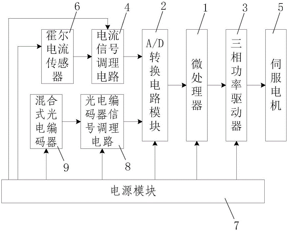
[0051] Such as figure 1 As shown, the absolute position signal correction value determination system of the hybrid photoelectric encoder of the present invention includes a microprocessor 1, a Hall current sensor 6 for real-time detection of the DC bus current that supplies power to the servo motor 5, and a system The power supply module 7 powered by each power unit in the power supply, the input terminal of the microprocessor 1 is connected with the A / D conversion circuit module 2 and the absolute position signal for the rotation of the servo motor 5 detected by the hybrid photoelectric encoder 9 and a photoelectric encoder signal conditioning circuit 8 for amplifying and filtering the relative position signal, the input terminal of the A / D conversion circuit module 2 is connected with a current signal conditioning circuit for amplifying and conditioning the signal output by the Hall current sensor 6 4. The output end of the Hall current sensor 6 is connected to the input end...


PUM


Abstract

The invention discloses a system and method for determining correction values of absolute position signals of a hybrid photoelectric encoder. The system comprises a microprocessor, a hall current sensor, a power supply module, an A / D conversion circuit module, a photoelectric encoder signal conditioning circuit, a current signal conditioning circuit and a three-phase power driver for driving a servo motor with the hybrid photoelectric encoder. The method comprises the following steps of (1) coaxially installing the hybrid photoelectric encoder and the servo motor; (2) obtaining installation error correction values of the hybrid photoelectric encoder; (3) obtaining the correction values of the absolute position signals when an installation error is not considered under the condition of not considering the installation error of the hybrid photoelectric encoder; and (4) determining the final error correction values of the absolute position signals of various sectors of the hybrid photoelectric encoder. The system and the method are reasonable in design, convenient to implement, low in cost, convenient to use and operate, high in correction efficiency, high in correction accuracy and high in practicability; manpower and material resources are saved; and promotion and application are facilitated.

Description

technical field [0001] The invention belongs to the technical field of encoder absolute position signal calibration, and in particular relates to a system and method for determining a correction value of an absolute position signal of a hybrid photoelectric encoder. Background technique [0002] In the field of servo motor control, in order to accurately control the position or speed and improve the control performance of the servo motor, it is often necessary to know the initial position of the rotor and the position and speed information during operation, which can be obtained by installing a rotor position sensor. Among them, the incremental photoelectric encoder with absolute position information U, V, W has the characteristics of initial positioning information, high position recognition accuracy, and moderate price, and is widely used in the field of motor rotor position and speed detection that requires initial positioning information. For hybrid photoelectric encoder...

Claims


Application Information

Patent Timeline
IPC IPC(8): H02K11/22H02K11/215H02K11/225H02K11/33H02K11/35
Inventor 张玉峰
Owner XIAN UNIV OF SCI & TECH
Why Eureka
Try Eureka