
Electronic communication device signal emitter

A technology for signal transmitters and communication equipment, applied in the field of transmitters, can solve the problems of unfavorable miniaturization of wireless transmitters, low signal anti-interference ability, high distortion rate, etc., and achieve the effect of low cost, no fear of distortion, and high stability

Inactive Publication Date: 2017-05-10
ZHENGZHOU BEIDOU COMM TECH
View PDF0 Cites 0 Cited by
  • Summary
  • Abstract
  • Description
  • Claims
  • Application Information

AI Technical Summary

Problems solved by technology

[0002] Frequency modulation transmitting circuits are widely used in electronic communication equipment. Frequency modulation is also called frequency modulation. It is a modulation method that makes the frequency of high-frequency oscillating signals change according to the law of the modulation signal while keeping the amplitude constant. There are many ways of frequency modulation, and now there are many Both technologies use crystal oscillator frequency modulation method, but most of the circuit design adopts integrated chip design, resulting in low signal anti-interference ability, high distortion rate, and high cost and large volume defects. For the miniaturization of wireless transmitters very unfavorable

Method used


Image

  • Electronic communication device signal emitter

Examples


Embodiment Construction

[0008] The following will clearly and completely describe the technical solutions in the embodiments of the present invention with reference to the accompanying drawings in the embodiments of the present invention. Obviously, the described embodiments are only some, not all, embodiments of the present invention. Based on the embodiments of the present invention, all other embodiments obtained by persons of ordinary skill in the art without making creative efforts belong to the protection scope of the present invention.

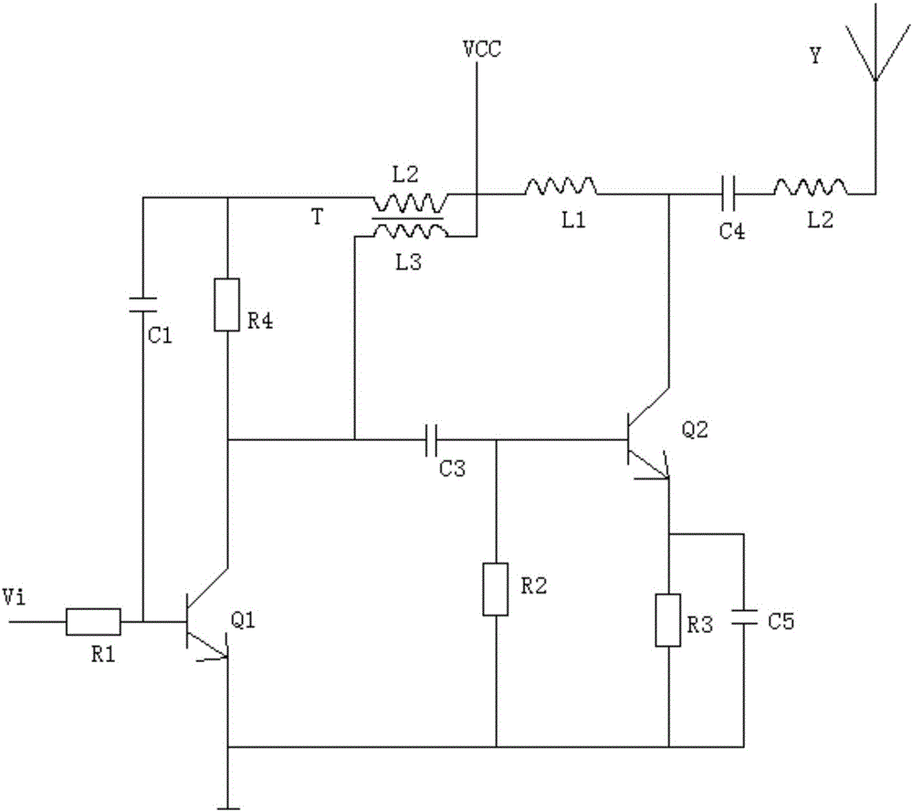
[0009] see figure 1 , in an embodiment of the present invention, an electronic communication device signal transmitter includes a triode Q1, a triode Q2, a resistor R1, a capacitor C1, an inductor L1, and a transformer T. One end of the resistor R1 is connected to an input signal Vi, and the other ends of the resistor R1 are respectively Connect the capacitor C1 and the base of the transistor Q1, the collector of the transistor Q1 is respectively connected to ...


PUM


Abstract

The invention discloses an electronic communication device signal emitter comprising a triode Q1, a triode Q2, a resistor R1, a capacitor C1, an inductor L1 and a transformer T, wherein one end of the resistor R1 is connected with an input signal Vi, the other end of the resistor R1 is respectively connected with the capacitor C1 and the base of the triode Q1, the collector of the triode Q1 is respectively connected with a resistor R4, a coil L3 of the transformer T and a capacitor C3, the other end of the coil L3 of the transformer T is connected with a power supply VCC, the other end of the capacitor C3 is respectively connected with a resistor R2 and the base of the triode Q2, the emitter of the triode Q2 is respectively connected with a resistor R3 and a capacitor C5, the other end of the capacitor C5 is respectively connected with the other end of the resistor R3, the other end of the resistor R2 and the emitter of the triode Q1 and is grounded, and the collector of the triode Q2 is respectively connected with the inductor L1 and a capacitor C4. The electronic communication device signal emitter provided by the invention has a simple circuit structure, and adopts the triodes, the transformer and some resistor-capacitor units for control, thereby being simple in circuit structure, low in cost, small in volume, high in stability and free of distortion.

Description

technical field [0001] The invention relates to a transmitter, in particular to a signal transmitter for electronic communication equipment. Background technique [0002] Frequency modulation transmitting circuits are widely used in electronic communication equipment. Frequency modulation is also called frequency modulation. It is a modulation method that makes the frequency of high-frequency oscillating signals change according to the law of the modulation signal while keeping the amplitude constant. There are many ways of frequency modulation, and now there are many Both technologies use crystal oscillator frequency modulation method, but most of the circuit design adopts integrated chip design, resulting in low signal anti-interference ability, high distortion rate, and high cost and large volume defects. For the miniaturization of wireless transmitters Very unfavorable. The invention provides a signal transmitter for electronic communication equipment with a simple circ...

Claims


Application Information

Patent Timeline
IPC IPC(8): H04B1/04
CPCH04B1/0475
Inventor 不公告发明人
Owner ZHENGZHOU BEIDOU COMM TECH
Learn More