Signal transmission method and network system

A network system and signal technology, applied in transmission systems, television systems adapted to optical transmission, cable transmission adaptation, etc., can solve problems such as increasing network costs

Active Publication Date: 2017-05-10
HUAWEI TECH CO LTD
View PDF8 Cites 2 Cited by
  • Summary
  • Abstract
  • Description
  • Claims
  • Application Information

AI Technical Summary

Problems solved by technology

[0005] However, in this technology, due to the need to

Method used


Image

  • Signal transmission method and network system
  • Signal transmission method and network system
  • Signal transmission method and network system

Examples


Embodiment Construction

[0034] The technical solutions in the embodiments of the present invention will be described below with reference to the drawings in the embodiments of the present invention.

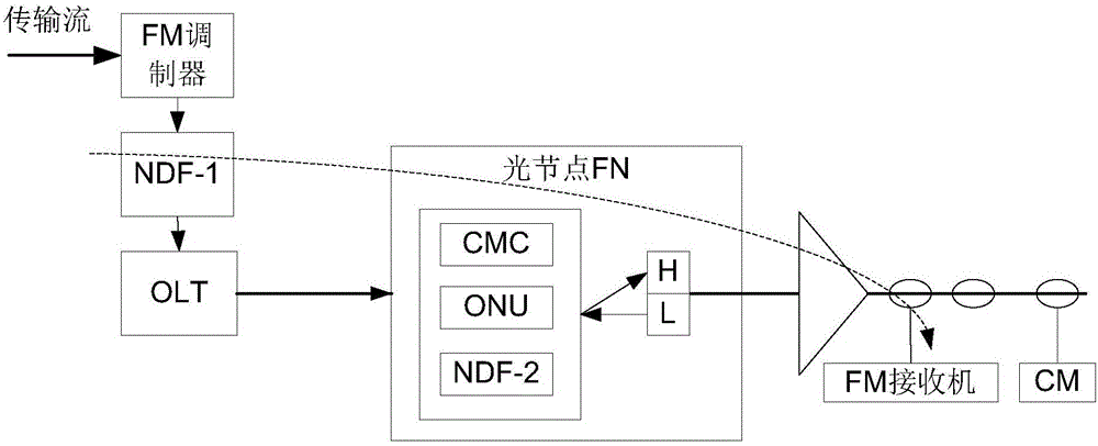
[0035] Such as Figure 4a As shown, in a multimedia information and communication system, usually after video and audio data is coded by a source, it must be multiplexed with auxiliary data to form an elementary stream (Elementary Stream, ES). After the ES is packaged, it forms a packaged elementary stream (Packetized Elementary Stream, PES). Subsequently, the PES representing different video and audio signals are sent to the transmission multiplexer for system multiplexing, and they are combined into a program stream (PS) in the program stream (Program Stream, PS) multiplexer, or in the transport stream (Transport Stream, TS) are combined into TS in the multiplexer. PS and TS are two types of data streams in the digital video system, which are defined by the MPEG-2 system layer. H.264 uses the same s...


PUM


Abstract

The invention discloses a network system. The network system comprises a decoding unit, a light transmitter TX, a digital/analogue converter, a FM modulator, a light receiver RX and a FM receiver, wherein the decoding unit is used for receiving a transmission stream so as to acquire a pulse coding modulation PCM code stream according to the transmission stream and provide the PCM code stream to the TX; the TX is used for converting the PCM code stream into a digital light signal, and sending the digital light signal to the RX through a digital optical fiber; the RX is used for receiving the PCM code stream and performing photoelectric conversion on the PCM code stream to obtain a digital electric signal; the FM modulator is used for modulating the digital electric signal and sending the digital electric signal to the digital/analogue converter; the digital/analogue converter is used for converting the digital electric signal into an analogue signal, and then providing the FM receiver with the analogue signal; and the FM receiver is used for receiving the analogue signal.

Description

technical field [0001] The application belongs to the technical field of communication, and relates to a signal transmission method and a network system. Background technique [0002] A cable television network (Community Antenna Television, CATV) is used to carry broadcast television signals. Such as figure 1 As shown, in a Hybrid Fiber-Coaxial (HFC) network, a FM (Frequency Modulation, FM) modulator receives a transport stream (Transport Stream, TS), and modulates the TS to obtain a radio frequency (Radio Frequency, RF) signal, the optical transmitter TX1 sends the RF signal to the optical receiver RX1 in the optical node (FiberNode, FN) through the analog fiber, and RX1 performs photoelectric conversion on the received RF signal and sends it to the modulation device for modulation to obtain an FM signal , FM signal reaches FM receiver 1 and / or FM receiver 2 via amplifier and coaxial cable. [0003] As the network technology shifts from analog technology to digital tech...

Claims


Application Information

Patent Timeline
IPC IPC(8): H04L29/06G10L19/16H04N21/61H04N7/10H04N7/22
CPCH04N7/10H04N7/22H04N21/6118G10L19/173H04L65/75H04L65/65
Inventor 雷俊鹏罗俊鲁珣刘杰
Owner HUAWEI TECH CO LTD
Why Eureka
Try Eureka