Gas turbine engine with a transition duct and corresponding method of manufacturing a transition duct

一种燃气涡轮、发动机的技术,应用在发动机功能、发动机元件、机器/发动机等方向,能够解决热梯度脱粘、龟裂等问题,达到延长寿命、减少停机时间、增加可用性的效果

Active Publication Date: 2017-05-10
SIEMENS ENERGY GLOBAL GMBH & CO KG
View PDF3 Cites 2 Cited by
  • Summary
  • Abstract
  • Description
  • Claims
  • Application Information

AI Technical Summary

Problems solved by technology

However, there is still a considerable thermal gradient across the transition duct and debonding and cracking of the TBC due to thermal stress has been found in service experience

Method used


Image

  • Gas turbine engine with a transition duct and corresponding method of manufacturing a transition duct
  • Gas turbine engine with a transition duct and corresponding method of manufacturing a transition duct
  • Gas turbine engine with a transition duct and corresponding method of manufacturing a transition duct

Examples


Embodiment Construction

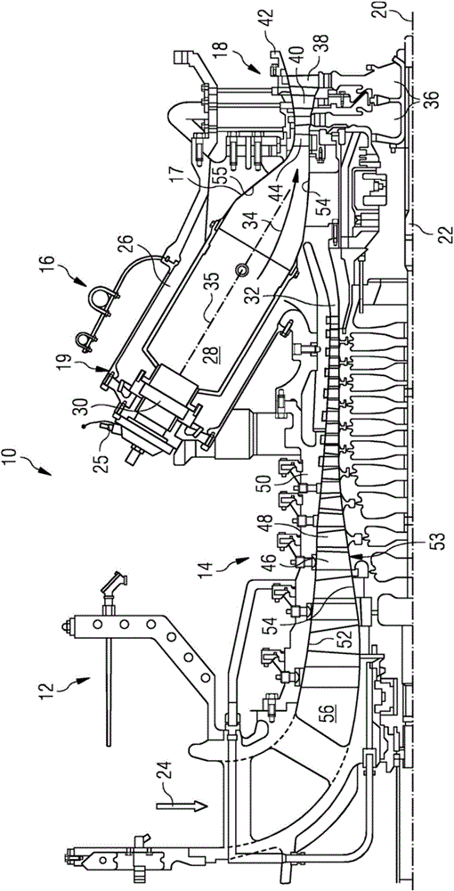
[0046] figure 1 An example of gas turbine engine 10 is shown in cross-section. Gas turbine engine 10 includes, in a flow sequence, an inlet 12 , a compressor section 14 , a combustor section 16 , and a turbine section 18 generally arranged in flow sequence and generally about and in the direction of a longitudinal or rotational axis 20 . Gas turbine engine 10 further includes a shaft 22 rotatable about an axis of rotation 20 and extending longitudinally through gas turbine engine 10 . Shaft 22 drivingly connects turbine section 18 to compressor section 14 .

[0047] In operation of gas turbine engine 10 , air 24 drawn through air inlet 12 is compressed by compressor section 14 and delivered to combustion or burner section 16 . The burner section 16 includes a burner plenum 26 , one or more combustion chambers 28 and at least one burner 30 secured to each combustion chamber 28 . Combustion chamber 28 and burner 30 are located inboard of burner plenum 26 . Compressed air pas...


PUM


Abstract

The invention discloses a gas turbine engine with a transition duct and a corresponding method of manufacturing a transition duct. The gas turbine engine (10) having a combustor (16), a turbine (18) and a transition duct (17), the transition duct (17) is located between the combustor (16) and the turbine (18) to channel hot gas (34) from the combustor (16) to the turbine (18). The transition duct (17) has an internal surface (54, 55, 56, 57) on which the hot gas (34) impinges to cause a varying temperature profile over the internal surface (54, 55, 56, 57). A thermal barrier coating (100) is located on the internal surface (54, 55, 56, 57) and comprises at least a first thermal barrier coating patch (72P) and a second thermal barrier coating patch (74P). The first thermal barrier coating patch (72P) having a first predetermined thickness (72T) located on the internal surface (54, 55, 56, 57) and within a first area (72A) subject to a higher temperature than an uncoated part of the internal surface (54, 55, 56, 57) and bounded by a first isotherm (73) of a first predetermined temperature. The second thermal barrier coating patch (74P) having a second predetermined thickness (74T) located on the internal surface (54, 55, 56, 57) and within a second area (74A) subject to a higher temperature than the uncoated part of the internal surface (54, 55, 56, 57) and bounded by a second isotherm (75) of a second predetermined temperature. The second predetermined temperature is higher than the first predetermined temperature and the second predetermined thickness (74T) is thicker than the first predetermined thickness (72T). A corresponding method of manufacturing a transition duct is also provided.

Description

technical field [0001] The present invention relates to transition ducts between the combustor and turbine sections of a gas turbine. Furthermore, the invention relates to a gas turbine comprising at least one transition duct and to a method for producing the transition duct. Background technique [0002] A gas turbine engine includes a compressor, a combustor, and a turbine arranged in a flow sequence and generally about an axis of rotation. During operation, the compressor supplies compressed air to the combustor and this compressed air is mixed with gaseous or liquid fuel. The air / fuel mixture is then combusted and the combustion gases are channeled to the turbine section via the transition duct. The combustion gases force the rotation of the turbine, which in turn drives the compressor via an interconnected shaft. For gas turbine engines having a can combustor arrangement, which is an annular array of combustor cans each having at least one burner and a combustion cha...

Claims


Application Information

Patent Timeline
Patent Type & Authority Applications(China)
IPC IPC(8): F01D9/02F01D25/08
CPCF01D9/023F01D25/08F05D2240/35F05D2260/231F05D2300/611
Inventor S·布雷威尔G·布拉特R·帕克
Owner SIEMENS ENERGY GLOBAL GMBH & CO KG
Why Eureka
Try Eureka