Device for changing the angle of inclination in wind turbines

A technology for wind turbines and tilt angles, which is applied in the field of tilt angle devices and can solve problems such as complex structures and expensive

Inactive Publication Date: 2017-05-10
纳巴风力公司
View PDF5 Cites 0 Cited by
  • Summary
  • Abstract
  • Description
  • Claims
  • Application Information

AI Technical Summary

Problems solved by technology

This would make the structure more complex and expensive

Method used


Image

  • Device for changing the angle of inclination in wind turbines
  • Device for changing the angle of inclination in wind turbines
  • Device for changing the angle of inclination in wind turbines

Examples


Embodiment Construction

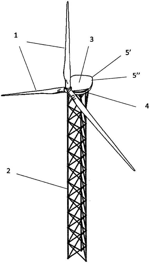
[0026] exist figure 1 In, the means for changing the pitch angle is mounted on a horizontal axis wind turbine having at least two blades (1) oriented by the wind and placed on a lattice tower (2) having at least three legs. An annular connection part (4) is provided between the nacelle (3) and the tower (2). Two anemometers (5) are mounted at the front end of the nacelle (3), one for measuring the horizontal component (5') and the other for measuring the vertical component (5"). These measurements are fed back to the control system, which Indicates how much the nacelle (3) should move relative to the horizontal ground plane.

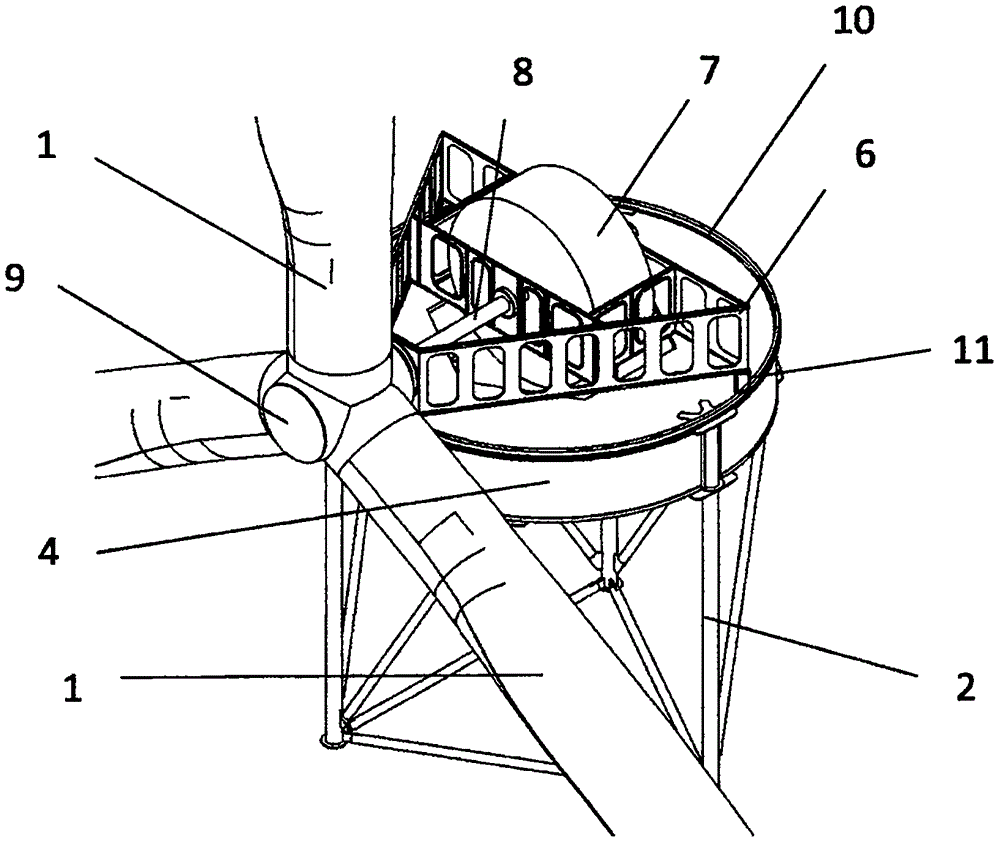
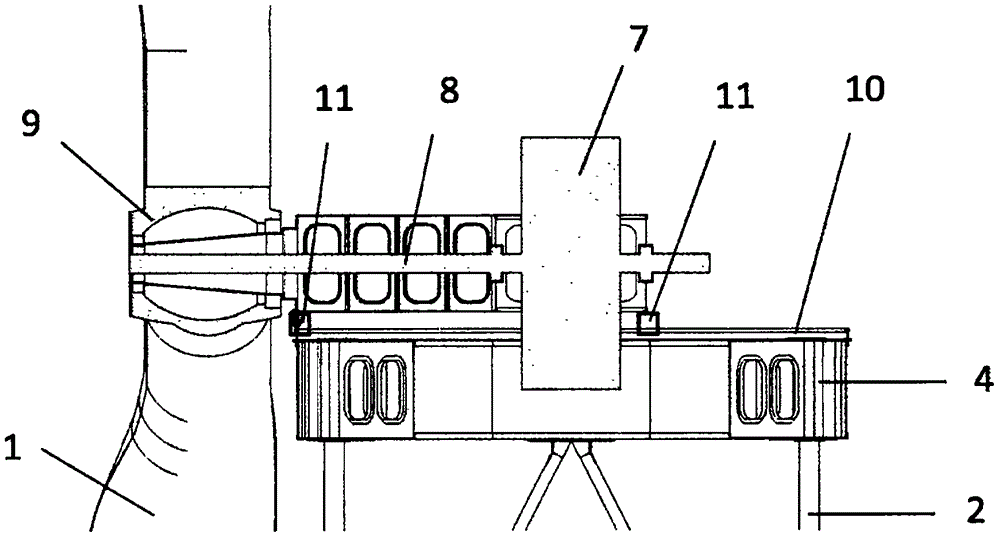
[0027] like figure 2 and image 3 As shown, a lattice tower (2) supports an annular connection part (4) on which a triangular pedestal (6) rests and houses a generator (7) and at one end a rotor (9). ) and spindle (8). The top of the annular link (4) has a ring or rolling track (10) forming part of the yaw system. The yaw system comprises the afor...


PUM


Abstract

The invention relates to a device for changing the angle of inclination (13) in wind turbines, which device is formed by a connection part (4) having a peripheral rolling ring (10) on which three support points (11), which support a bed (6) where the power train is supported, roll, thereby permitting the orientation of the yaw angle. At least one line of pistons (14) and their corresponding cylinders (15) are provided on each of the rolling support points (11), anchored to the bed (6) via a plate (16) for each group of actuators, thereby integrating the yaw and tilt actuation systems. When the cylinder (15) pushes or retracts the piston (14) and the piston (14) extends or retracts the ring-shaped connection part (4) (the fixed part), and the bed (6) that supports the power train (the mobile part) displacing a certain angle [alpha], the piston (14), which is articulated (17) in the lower end thereof, progressively inclines in proportion to the angle of inclination a. The degree of inclination reached, for a leeward wind turbine, is based on the measurements of respective anemometers (5) established in the front portion of the nacelle (3).

Description

technical field [0001] The present invention is included in the field of wind turbines and, more particularly, relates to devices capable of varying the angle of inclination (tilt) formed by the rotor shaft with respect to the horizontal. Background technique [0002] The original intention of the rotor shaft tilt is not to align with the wind direction. Instead, it is envisaged to increase the space between the blade and the tower to prevent collisions. This increase is very significant against the wind, as the greatest blade deflection is bent towards the tower. In this case, the inclination results in a certain horizontal wind deviation, which is exacerbated when the wind has a vertical component (especially on complex terrain). However, this effect is reversed for downwind rotors. Firstly, the greatest blade deflection faces outwards, and thus no pitching is required. However, this angle improves alignment with the vertical wind component. Thus, a disadvantage of ge...

Claims


Application Information

Patent Timeline
Patent Type & Authority Applications(China)
IPC IPC(8): F03D7/02
CPCF03D1/00F05B2240/2213F05B2270/321F03D7/02F03D9/25Y02E10/72Y02E10/728F03D7/0204F03D13/20
Inventor P·E·桑斯H·R·萨维·科斯塔
Owner 纳巴风力公司
Why Eureka
Try Eureka