Solid-liquid separation device for oil slurry and solid-liquid separation system for oil slurry

A technology of solid-liquid separation and oil slurry, which is applied in the direction of filtration separation, separation method, and treatment of hydrocarbon oil, etc. It can solve the problem that the filtration separation process is difficult to meet the long-term stable work, there is no major technical improvement in swirling and filtration, and the process flow unequal problem

Inactive Publication Date: 2017-05-17
SINOPEC ENG GRP CO LTD
View PDF9 Cites 4 Cited by
  • Summary
  • Abstract
  • Description
  • Claims
  • Application Information

AI Technical Summary

Problems solved by technology

[0005] For example, the patent No. CN201010577004.8 discloses a device and method for separating residues from catalytic cracking oil slurry, using multiple filter groups; for example, the patent No. CN201210530805.8 discloses a catalytic cracking device The oil slurry filtration system has different technological processes, but both stages use filtration; among them, the latter explains the two-stage filtration mechanism more deeply, but there is no essential difference
As the catalytic cracking oil slurry presents the characteristics of inferior and heavy quality, the existing single filtration separation process is difficult to meet the long-term stable work
For example, the patent No. CN201020213529.9 discloses the catalytic cracking oil slurry filtration equipment and mentions the use of cross-flow filters, which still rely on filtration technology. According to the industrial operation situation, it is still difficult to meet the requirements of long-term stable work.
The patent No. CN201120188596.4 jointly declared by China University of Petroleum and SEI discloses a continuous filtration device for catalytic oil slurry and the patent No. CN201120188613.4 discloses a kind of catalytic oil slurry filtration device. Both of them refer to the combination of swirling flow and filtration process, but no major technical improvements to swirling and filtration

Method used


Image

  • Solid-liquid separation device for oil slurry and solid-liquid separation system for oil slurry
  • Solid-liquid separation device for oil slurry and solid-liquid separation system for oil slurry
  • Solid-liquid separation device for oil slurry and solid-liquid separation system for oil slurry

Examples


Embodiment 1

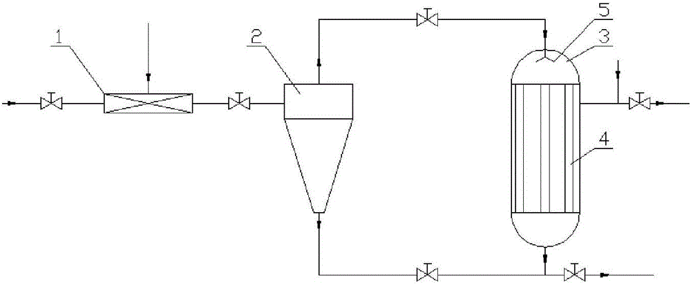
[0036] Such as figure 1 -3, the slurry solid-liquid separation device provided in this embodiment includes at least one mixer 1, at least one primary separator 2 connected to each mixer 1, and connected to each primary separator 2 Pass through at least one secondary filter 3 .

[0037] It should be pointed out here that the purpose of the mixer 1 and the primary separator is to ensure that the filter will not be contaminated with colloid-rich oil slurry and that the filter tube will not be blocked. At the same time, with the help of cross-flow filtration technology, the entire system can basically Realize continuous work without backwashing.

[0038] Specifically, each specific structure of the slurry solid-liquid separation device in this embodiment will be described in detail below:

[0039] For mixer 1, it is an auxiliary mixer.

[0040] It should be pointed out that the auxiliary agent mixer can be a conventional static mixer, or a Venturi ejector, preferably a Venturi ej...

Embodiment approach

[0048] Such as figure 1 As shown, in the first alternative of this embodiment, a mixer 1, a primary separator 2 and a secondary filter 3 are included; the mixer 1 communicates with the primary separator 2, and the The primary separator 2 communicates with the secondary filter 3;

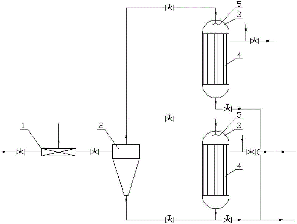
[0049] Such as figure 2 As shown, in the second alternative of this embodiment, a mixer 1, a primary separator 2 and two secondary filters 3 are included; the mixer 1 communicates with the primary separator 2, The primary separator 2 is in communication with the two secondary filters 3;

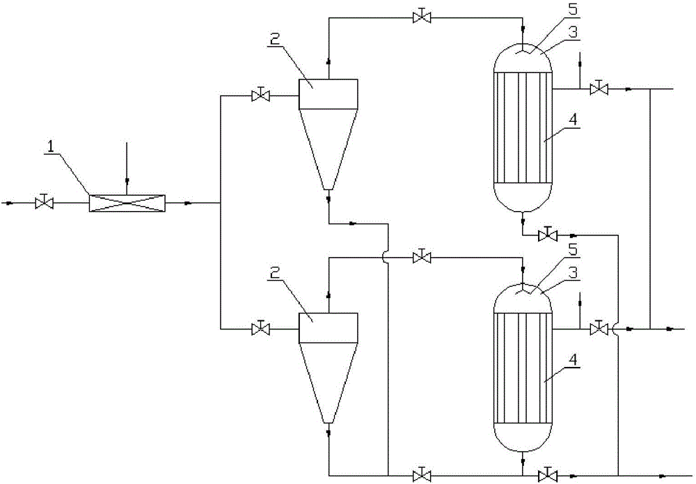
[0050] Such as image 3 As shown, in the third alternative of this embodiment, a mixer 1, two primary separators 2 and two secondary filters 3 are included; the mixer 1 and the two primary separators 2 The two primary separators 2 communicate with the two secondary filters 3 respectively.

[0051] It should be pointed out that in this embodiment, the number and combinations of the mixer 1, the primary separato...

Embodiment 2

[0055] On the basis of Embodiment 1, this embodiment also provides an oil slurry solid-liquid separation system, including the above-mentioned oil slurry solid-liquid separation device.

[0056] In this implementation, the oil slurry solid-liquid separation system also includes an automatic control system (not shown) on the basis of all mentioned oil slurry solid-liquid separation devices in the first embodiment. The automatic control system is electrically connected with the solenoid valve, which can Automatically adjust the opening and closing of the solenoid valve to improve the working efficiency of the system and save labor.

[0057] The oil slurry solid-liquid separation system provided in this embodiment includes the above-mentioned oil slurry solid-liquid separation device, so it has all the advantages of the oil slurry solid-liquid separation device, and will not be described in detail here.

[0058] To sum up, the purpose of auxiliary aid and first-stage separation i...


PUM


Abstract

The invention provides a solid-liquid separation device for oil slurry and a solid-liquid separation system for oil slurry. The solid-liquid separation device for oil slurry comprises at least one mixer, at least one first-level separator and at least one second-level filter; the first-level separator is communicated with each mixer; the second-level filter is communicated with each first-level separator. Different from a traditional single filtering and separating technology, the invention adopts the first-level separation and the second-level filtering, so that the solid-liquid separation device for oil slurry can meet the requirement of long-period stable work.

Description

technical field [0001] The invention belongs to the field of solid-liquid separation of oil slurry thrown outside a catalytic cracking unit, and relates to a combined process for solid-liquid separation of oil slurry thrown outside a catalytic cracking unit, in particular, to an oil slurry solid-liquid separation device and an oil slurry solid-liquid separation The separation system is especially effective for oil slurries containing colloids and asphaltenes. Background technique [0002] In my country, catalytic cracking units generally blend vacuum residue or atmospheric heavy oil, both of which belong to heavy oil catalytic cracking. In recent years, although the catalytic cracking process faces the competition of hydrocracking, it is still the main means of lightening heavy oil and an important way for refineries to obtain economic benefits. In recent years, due to the heavy weight of raw materials and the increase in the proportion of slagging in refineries, the proces...

Claims


Application Information

Patent Timeline
IPC IPC(8): C10G53/02B01D36/04
CPCB01D36/04B01D36/045C10G53/02C10G2300/80
Inventor 陈强蔡连波李小婷赵晓青盛维武
Owner SINOPEC ENG GRP CO LTD
Why Eureka
Try Eureka