

Hydraulic driver and vehicle thereof
A transmission and hydraulic technology, which is applied in the field of hydraulic mechanical systems, can solve problems such as high labor intensity, low transmission efficiency, and high failure rate, and achieve the effects of high transmission efficiency, weight reduction, and cost reduction
- Summary
- Abstract
- Description
- Claims
- Application Information
AI Technical Summary
Problems solved by technology
Method used
Image

Examples
Embodiment Construction
[0048] Embodiments of the present invention will be further described below.
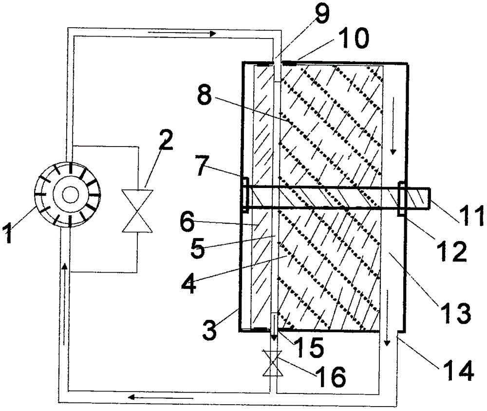
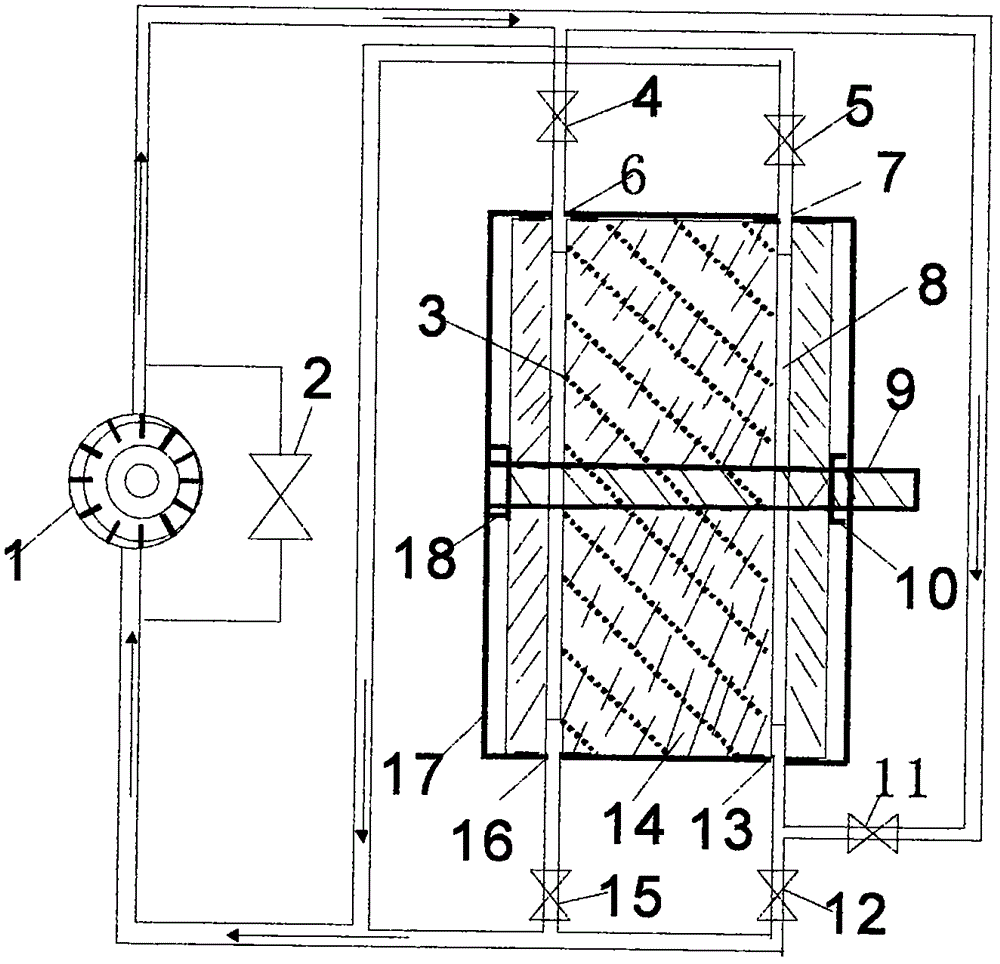
[0049] A hydraulic transmission, including a hydraulic mechanical system, the executive element is a three-port single-ended annular oil distribution chamber screw rotor follower, wherein the annular oil distribution chamber has one port at the inlet and outlet, one port at the discharge chamber, and the output end of the oil pump is connected to the The input port of the annular oil distribution chamber of the driven machine of the screw tube rotor is connected with oil, one of the input ports of the oil pump is connected with the oil port of the output port of the annular oil distribution chamber of the driven machine of the screw tube rotor through the oil pipe with valves, and the other oil pipe is connected with the port of the discharge chamber. Close the valve, when the prime mover drives the oil pump to circulate the working medium oil, hydraulic pressure is generated in the annular oil distr...
PUM
 Abstract
Description
Claims
Application Information