Indoor planter using fan for accelerating air flowing

A technology of air flow and planter, applied in the field of indoor air purification, can solve the problems of poor PM2.5 treatment capacity, insufficient indoor air purification capacity, insufficient photosynthesis, etc., and achieve compact structure, simple structure, and improved air quality Effect

Active Publication Date: 2017-05-17
ZHONGSHAN ZHONGCHENG PACKING PROD
View PDF10 Cites 3 Cited by
  • Summary
  • Abstract
  • Description
  • Claims
  • Application Information

AI Technical Summary

Problems solved by technology

[0005] The object of the present invention is to provide an indoor planter that utilizes a fan to accelerate air flow, so as to solve the problems of poor ventilation and poor air permeability, insufficient photosynthesis, and insufficient indoor air purifica...

Method used


Image

  • Indoor planter using fan for accelerating air flowing
  • Indoor planter using fan for accelerating air flowing
  • Indoor planter using fan for accelerating air flowing

Examples


Embodiment 1

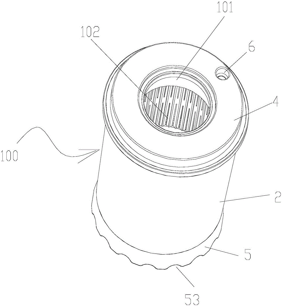
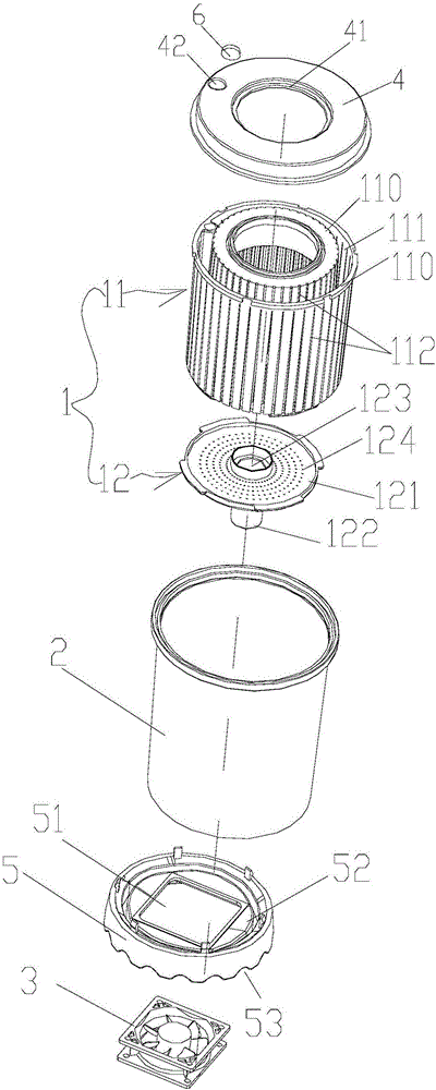
[0059] Such as Figure 1 to Figure 14 As shown, an indoor planter utilizing a fan to accelerate air flow includes a container body 100 for planting plants, and the container body 100 is provided with a container opening 101 for plants 200 to grow towards the outside of the container body 100; A chamber 102 connected to the mouth 101, soil can be placed in the chamber 102 for plant roots 201 to grow; a water storage seat 28 located below the chamber 102 and communicated with the chamber 102 to provide moisture to the chamber 102;

[0060] The container body 100 includes an inner cylinder 1 and an outer cylinder 2 sleeved outside the inner cylinder 1; the inner cylinder 1 includes an inner cylinder side wall 11 and an inner cylinder bottom wall 12 arranged at the lower end of the inner cylinder side wall 11, the inner cylinder 1. The upper end is opened to form the container mouth 101. The inner cylinder side wall 11 and the inner cylinder bottom wall 12 enclose the chamber 102....

Embodiment 2

[0076] The structure of this embodiment is basically the same as that of Embodiment 1, the difference is: the shape of the container body 100 is a rectangle, and the cross-sectional outline shape of the wall 110 of the outer cylinder 2 and the inner cylinder 1 is a rectangle, such as Figures 15 to 19 As shown, two fans 3 are used, and the side wall 11 of the inner cylinder is composed of 4 layers of walls 110 at a certain distance from each other, forming 3 filter cavities. A filter cavity 111 for placing air filter media is formed between two adjacent walls 110 , and several air inlets 112 are provided on each wall 110 .

Embodiment 3

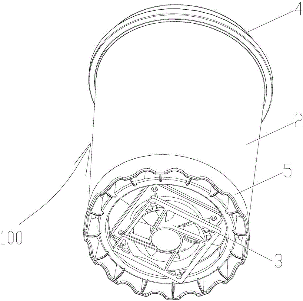
[0078] This embodiment is a modification of the structure of Embodiment 1, and the difference is that only the structure of the inner cylinder 1 is modified, and the inner cylinder 1 includes an inner cylinder side wall 11 and an inner cylinder arranged at the lower end of the inner cylinder side wall 11 Bottom wall 12, the upper end of the inner tube 1 is open to form the container mouth 101, the inner tube side wall 11 and the inner tube bottom wall 12 enclose the chamber 102, and the inner tube side wall 11 is only composed of one layer of walls 110 (cancel the original The structure of filter cavity 111 of embodiment one), wall 110 is all provided with some air inlets 112; There is a certain space between the cylinder side wall 21 and the inner cylinder side wall 11 to form an air flow channel 22, and the air flow channel 22 forms a flow channel inlet 23 at the bottom; an electric fan 3 is installed next to the container body 100, and the electric fan 3 Blow the air into t...


PUM


Abstract

The invention provides an indoor planter using a fan for accelerating air flowing. The indoor planter comprises a container body, wherein the container body is provided with a container port and a containing chamber, and a liquid storage holder is arranged below the containing chamber; the container body comprises an inner barrel and an outer barrel arranged outside the inner barrel in a sleeving mode; the sidewall of the inner barrel is at least composed of two layers of walls, a filter cavity is formed between the two adjacent walls, a plurality of air inlet holes are formed in each layer of wall, an air flowing channel is formed between the sidewall of the outer barrel and the sidewall of the inner barrel, and a flowing channel inlet is formed in the bottom of the air flowing channel; and an electric fan is installed beside the container body, air is blown into the air flowing channel from the flowing channel inlet by virtue of the electric fan or air in the air flowing channel is extracted away from the flowing channel inlet by virtue of the electric fan to form a positive pressure or a negative pressure in the air flowing channel, so that air flows directionally from the air inlet holes, the filter cavity, the containing chamber and the container port. The indoor planter greatly accelerates ventilation for the roots of plants planted by the planter, greatly improves the air permeability of soil, and enables the roots of the plants to grow with a full load; and the air purification capacity is eight times that of a common planter.

Description

technical field [0001] The invention relates to an indoor planter which uses a fan to accelerate air flow, and is mainly used for indoor air purification. Background technique [0002] Although the existing indoor planters on the market can absorb indoor CO2 and release oxygen by planting plants, their purification function is far from enough for areas with serious air quality index PM2.5, and different harmful particles in the air are still It exists indoors, so it needs to continue to improve its functions. In addition, indoor planters, because of the poor ventilation of the plant roots and the poor air permeability of the soil, it is difficult to stretch at all, it is difficult to absorb oxygen and nutrients, and the photosynthesis is not sufficient; resulting in the absorption of indoor CO2 and the release of oxygen and negative ions ability to decline. [0003] As we all know, plants can purify the air by inhaling carbon dioxide, releasing oxygen or inhaling toxic gas...

Claims


Application Information

Patent Timeline
IPC IPC(8): F24F1/00F24F3/16F24F13/28
CPCF24F1/00F24F13/28F24F8/10F24F8/175Y02B30/70
Inventor 黄好芳
Owner ZHONGSHAN ZHONGCHENG PACKING PROD
Why Eureka
Try Eureka