Method for detecting clogging of subsurface flow constructed wetland

一种人工湿地、探测方法的技术,应用在潜流人工湿地堵塞的探测领域,能够解决二次污染、操作复杂、观察法滞后性等问题,达到便于计算、操作简单、实用价值高的效果

Active Publication Date: 2017-05-17
SHANDONG UNIV
View PDF5 Cites 14 Cited by
  • Summary
  • Abstract
  • Description
  • Claims
  • Application Information

AI Technical Summary

Problems solved by technology

These methods have great defects in the promotion and application process, among which the observation method has serious hysteresis; the clogging substance measurement method can only perform qualitative analysis; the permeability coefficient method is limited to the measurement of a certain point, and the operation is relatively complicated; The chemical method can only evaluate the wetland as a whole, and it will cause secondary pollution

Method used


Image

  • Method for detecting clogging of subsurface flow constructed wetland
  • Method for detecting clogging of subsurface flow constructed wetland
  • Method for detecting clogging of subsurface flow constructed wetland

Examples


Embodiment 1

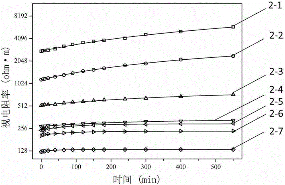
[0032] After the water body is emptied, the apparent resistivity of fillers with different clogging degrees changes with time.

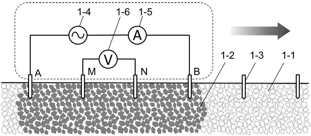
[0033]The constructed wetland of this embodiment adopts artificially produced subsurface flow constructed wetland models of different degrees of blockage, such as figure 1 As shown, the apparent resistivity of fillers with different clogging degrees is measured using the Wenner method. Electrodes 1-3 use copper rods with a diameter of 1.5 cm. The length of electrodes 1-3 is 20 cm. The distance is 40cm. The two adjacent electrodes M and N are measuring electrodes. The measuring electrodes are connected to the voltmeter 1-6. The two electrodes A and B on both sides of the measuring electrodes are the power supply electrodes. The power supply electrodes are connected to the AC power supply 1-4 and the ammeter 1- 5.

[0034] After the water body in the wetland bed is emptied, the apparent resistivity measurement is started. During the measurement, an AC...

Embodiment 2

[0037] Distribution of apparent resistivity in different areas of subsurface flow wetlands with blockage.

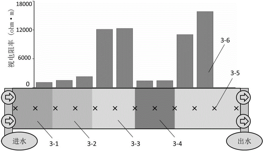
[0038] The constructed wetland of this embodiment adopts artificially produced subsurface flow constructed wetland models of different degrees of blockage, such as image 3 As shown, the front end of the subsurface constructed wetland bed is the clogged area 3-1 with a sediment specific gravity of 15%, followed by the clogged area 3-2 with a sediment specific gravity of 10%, and the non-clogged area 3-3 after that. This phenomenon is The blockage caused by the sedimentation of particulate matter at the water inlet of the subsurface wetland; in the middle of the unblocked area is the blocked area 3-4 with a sediment specific gravity of 25%. This type of blockage is a regional blockage caused by uneven water flow inside the subsurface wetland.

[0039] Electrodes 3-5 use iron rods with a diameter of 1.5cm. The electrodes 3-5 are inserted into the filler to a depth of 15cm ...


PUM


Abstract

The invention discloses a method for detecting clogging of a subsurface flow constructed wetland, and is mainly used for detecting clogging of a subsurface flow constructed wetland. In the invention, based on the characteristic that deposits contained in a subsurface flow wetland clogged region can enhance the water retention capability, by means of the characteristics that after the moisture of a subsurface flow wetland is drained, the water content of a wetland bed increases with the increase of the clogging degree and the apparent resistivity of the wetland bed accordingly decreases with the increase of the clogging degree, the apparent resistivity of a determined region is measured and calculated by a Wenner method resistivity measurement technology; the clogged region is positioned and the clogging degree is judged according to the magnitude of the apparent resistivity. According to the invention, the clogged region can be accurately positioned, and the relative clogging degree of the clogged region can be judged, thereby providing technical support for sustainable operation of the subsurface flow constructed wetland. The method disclosed by the invention has the advantages of high precision, low damage, simple operation, low implementation cost and the like.

Description

technical field [0001] The invention relates to a detection method for subsurface flow artificial wetland blockage, belonging to the technical field of ecological environment protection. Background technique [0002] The application of constructed wetland system in the advanced treatment of sewage has the advantages of low construction and operation costs, strong operation, strong treatment capacity, and consideration of landscape effects, and it is more and more widely used. Subsurface flow constructed wetland sewage treatment is completed under the joint action of microbial degradation, plant absorption, and filler adsorption. Compared with the surface flow wetland, the water flow mode and structural characteristics of the subsurface constructed wetland improve the microbial sewage purification ability, and can reduce the impact of seasonal changes and the problem of mosquito breeding, but the subsurface constructed wetland filler plugging problem affects the reliability o...

Claims


Application Information

Patent Timeline
Patent Type & Authority Applications(China)
IPC IPC(8): G01N27/04G01V3/06
CPCG01N27/048G01V3/06C02F3/006C02F3/327C02F2209/05C02F2209/42G01N27/043Y02W10/10
Inventor 张建刘华清胡振张成禄范金林
Owner SHANDONG UNIV
Why Eureka
Try Eureka